!
ATTENTION
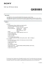
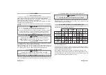
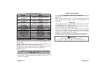
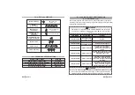
Engine immobilizer NC contact
Auxiliary negative input
Ground
Engine immobilizer NO contact
Engine immobilizer relay common
Positive
Positive under key
- 1 -
- 4 -
- 7 -
- 9 -
- 10 -
- 15 -
- 16 -
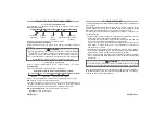
GREY
BROWN
YELLOW/GREEN
WHITE/GREY
WHITE
RED
YELLOW
WIRE COLOUR
WIRE FUNCTION
PIN
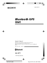
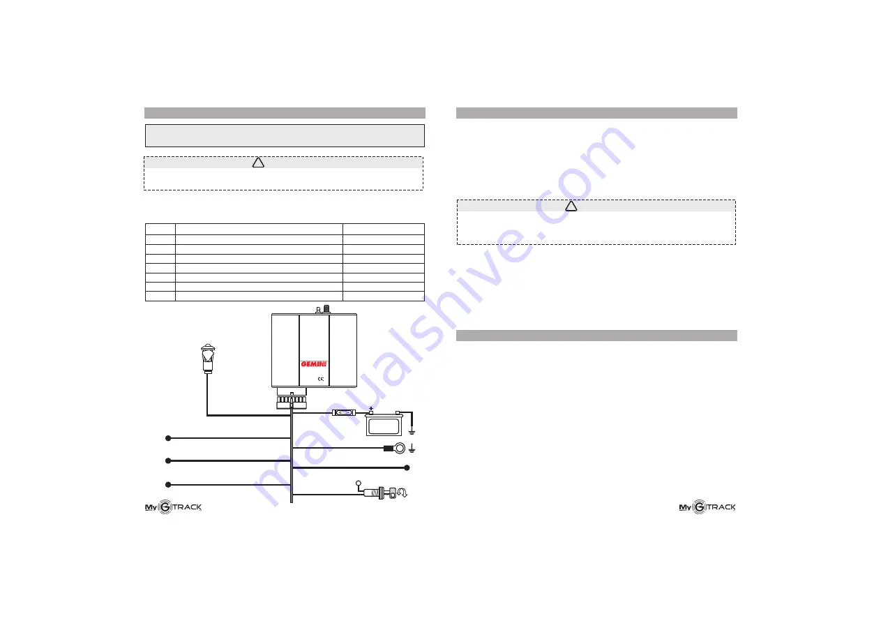
YELLOW
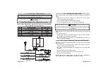
+30
Ignition
BROWN
Ground
RED
BLACK
RED
+
Battery
12 VOLT
Engine immobilizer relay (NC)
Engine immobilizer relay (NO)
Engine immobilizer relay
(common)
Auxiliary input (negative)
GREY
WHITE-GREY
WHITE
YELLOW-GREEN
JA
Made in Italy
For all EU
7892
ALARM SYSTEMS
13.0 - ELECTRICAL CONNECTIONS
NB
).
: available vehicle model specification sheets can be downloaded:
www.gemini-alarm.com (private area
Unplug the battery negative
before making any electric connection and
only reconnect it once all the connections have been made.
14.0 -
:
).
.
.
!
!
!
SYSTEM CONFIGURATION
After wring connections are completed, activate and configure the system as
follows
Make sure the SIM card is properly inserted and power the system
(reconnect the battery negative pole
Move the vehicle outside for better satellite reception
Turn ignition key ON for approx. 1 minute to get valid GPS data
15A
!
ATTENTION
If you are unsure whether the first initialization has been done correctly,
repeat the operation by disconnecting the module and reconnecting it after
a few minutes.
15.0 -
MyGTRACK systems are electronic devices which require suitable installation
and maintenance.
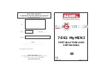
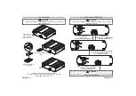
Fit the module in a horizontal position respect to the vehicle axis, in a well-
hidden position inside the vehicle cabin.
The module must be installed away from heat sources and potential water
infiltrations.
Only use manufacturer-specified voltages.
Do not clean the unit with water but use a damp cloth to wipe.
Do not remove warranty labels.
GEMINI TECHNOLOGIES DECLINES ANY LIABILITY FOR DAMAGES TO
THE SYSTEM DUE TO IMPROPER USE OR INSTALLATION.
!
!
!
!
!
CONTROL UNIT INSTALLATION AND MAINTENANCE
If the system has been properly initialized, remotely configure the system as
follows
Turn ignition key OFF.
Send an SMS with the configuration string to the phone number of the SIM-
card installed in the unit (see par. 5.0 and 8.0).
If correctly configured, you will receive a confirmation SMS; otherwise you
will receive an error message.
!
!
!
:
Connect the unit positive to the
nnect the negative output to the vehicle chassis.
battery positive terminal or to one of its shunts
and con