
Page 5
15
16
17
18
19
20
21
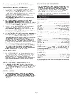
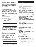
SCALE READING
CARTRIDGE HEIGHT
(mm)
0
1
2
3
4
5
6
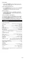
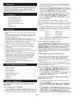
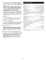
L (WHITE)
R (RED)
GND (Spade Lug)
MIXER OR
RECEIVER
OUTPUT CONNECTORS
PHONO L CHANNEL
PHONO R CHANNEL
GND Screw
7. After adjusting the horizontal zero (0) balance, turn the balanced
COUNTERWEIGHT (8) counter clockwise until the cartridge
manufacturer’s recommend stylus pressure appears on the STYLUS
PRESSURE RING (11) where it meets the center line of the TONE ARM
(6) rear shaft.
ADJUSTING THE ANTI-SKATING CONTROL:
Set the ANTI-SKATING CONTROL (12) to the same value as the stylus
pressure.
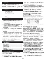
ADJUSTING TONE ARM HEIGHT:
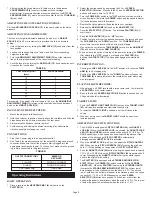
The tone arm height is adjustable between 0 and 6 mm. A HEIGHT
SCALE (14) (in 0.5 mm increments) is provided to aid in an accurate
setting.
1. Unlock the tone arm by turning the ARM LOCK (15) knob away from the
lock position.
2. Look up the cartridge height on Table A and find its corresponding
height scale reading.
3. Turn the ARM HEIGHT ADJUSTMENT RING (13) until the reference
line on the ring is positioned at the correct scale reading.
4. Lock the tone arm by turning the ARM LOCK (15) knob clockwise until
it reaches the lock position.
TABLE A
For example, if the height of the cartridge is 18.5 mm, the ARM HEIGHT
ADJUSTMENT RING (13) reference line should be positioned between 3
and 4 on the HEIGHT SCALE (14).
INSTALLING THE DUSTCOVER:
1. Mount the hinges onto the dustcover.
2. Hold the dustcover in position, directly above the turntable, and slide the
hinge bases into the holders mounted on the rear panel.
3. Always raise the dustcover before removal.
4. Avoid opening and closing the dustcover during play. Undesirable
vibration and stylus skipping can result.
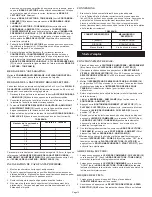
CONNECTIONS:
1. Plug the AC power plug into an appropriate outlet.
2. See Table A for proper connection of the output RCA plugs and ground
connector. Make sure that all the plugs are firmly plugged into the
appropriate jacks (phono inputs). To reduce hum, make sure the ground
lug is firmly connected to the ground screw.
TABLE B
Operating Instructions
BASIC OPERATION:
1. Place a record on the NEOPRENE MAT (4) which sits on the
PLATTER (2).
2. Select the desired speed by depressing the 33 or 45 SPEED
SELECTOR (18) button. Press both the 33 and 45 SPEED SELECTOR
buttons at the same time for 78 RPM.
3. Turn the POWER (16) switch to the “ON” position, at which point the
strobe illuminator (built into the POWER switch and the speed indicator
(for the selected speed) will illuminate.
4. Remove the stylus protector (if applicable to your cartridge).
5. Release the ARM CLAMP (9) found on the ARM REST (10).
6. Push the START STOP (17) button. The turntable PLATTER (2) will
start to spin.
7. Push the CUE LEVER (19) to the “UP” position.
8. Position the tone arm over the desired position on the record and push
the CUE LEVER to the “DOWN” position. The TONE ARM (6) will
slowly lower onto the record at which time play will begin.
9. When play is over, raise the TONE ARM (6), move it to the ARM REST
(10), and secure it with the ARM CLAMP (9).
10. You now have the option of turning off the power by turning the POWER
(16) switch to the “OFF” position, or stopping the PLATTER (2) by
pushing the START STOP (17) button and engaging the electronic
brake.
INTERRUPTING PLAY:
1. Pushing the CUE LEVER (19) to the “UP” position will cause the TONE
ARM (6) to lift, stopping play.
2. Pushing the CUE LEVER (19) to the “DOWN” position will cause the
TONE ARM (6) to slowly lower onto the record at the point where play
was interrupted.
PLAYING 45 RPM RECORDS:
1. When playing a 45 RPM record with a large center hole, first place the
45 ADAPTER on the center spindle.
2. Be sure that the 45 SPEED SELECTOR (18) button is pushed and the
45 speed indicator is illuminated.
TARGET LIGHT:
1. Push the TARGET LIGHT SWITCH (21) firmly and the TARGET LIGHT
(22) will raise into position and illuminate the stylus tip.
2. To lower the TARGET LIGHT, push down on it until it locks in the
casing.
3. When not being used, the TARGET LIGHT should be kept in the
lowered position.
ADJUSTING THE PITCH CONTROL:
1. The SA-2400 is equipped with PITCH CONTROL (24) and QUARTZ
LOCK (26). When the QUARTZ LOCK is activated, the QUARTZ LOCK
LED (25) lights GREEN, and the speed will be exactly 33 1/3, 45 or 78
RPM depending on which speed has been selected regardless of the
position of the pitch control. PITCH CONTROL automatically
disengages when QUARTZ LOCK is activated.
2. When the QUARTZ LOCK is off, you can adjust the PITCH CONTROL
(24). When you move PITCH CONTROL (24) off center, the pitch can
vary +/- 10% depending on the position of the PITCH CONTROL.
3. Push the QUARTZ LOCK (26) button to bring the speed back to exactly
33 1/3, 45 or 78 RPM when the PITCH CONTROL (24) is positioned off
center. Disengaging the QUARTZ LOCK will bring the platter speed
back to the original pitch setting.
4. The PLATTER (2) is equipped with a STROBE RPM INDICATOR
STRIP (27) and the POWER (16) switch contains built in STROBE
LIGHTS (28). When the PLATTER is spinning, the STROBE LIGHTS
illuminate the STROBE RPM INDICATOR STRIP. The bottom row of
dots will appear to be stationary when the pitch is -3.3%. The second
row of dots from the bottom will appear to be stationary when the speed
is exactly 33 1/3, 45 or 78 RPM depending on which SPEED
SELECTOR (18) buttons are pushed. The third row of dots from the
bottom will appear to be stationary when the pitch is +3.3%. The top row
of dots will appear to be stationary when the pitch is +7.2%.
Summary of Contents for SA-2400
Page 3: ...Page3 Figure 2 Figure 3...