background image

(5)

(5)

(5)

(5)

(5)

BASIC CONNECTIONS:

Connect the receiver output to the audio mixer or amplifier input, using a

standard audio cable with XLR connectors or 1/4” phone plugs.  Never

use the balance & unbalanced  outputs at the same time!  This may

cause signal loss or increased noise.

SETTING UP:

Prior to setting up, check that the transmitter and receiver are tuned to

the same frequency. Two or above transmitters operating in the same

frequency can not be used at the same time and area, so please select

the different frequencies which can be used simultaneously at local area.

CONNECTING THE RECEIVER TO POWER:

• Point the antennas upward.

• Check that the voltage of the supplied AC adapter (AC110 or AC220)

conforms to the voltage available in local area. Using the wrong AC

adapter may cause irreparable damage to the unit.

• Plug the feeder cable of the supplied AC adapter into DC IN socket on

the receiver. Then plug the AC adapter into a power outlet.

CONNECTING THE RECEIVER TO AN AUDIO MIXER

OR AN AMPLIFIER:

In order to make sure the sound quality and avoid distortion, please

adjust the volume level according to following instructions.

INSERTING BATTERIES INTO THE HANDHELD /

BODYPACK TRANSMITTER:

• Push to open the battery cover and insert batteries into the battery

compartment conforming to the polarity (+)(-) marks. The transmitter can

not work with incorrectly inserted batteries.

• When push the ON/OFF switch to “ON” to switch the power on, the LED

will flash momentarily. If the battery has sufficient power, the LED flashes

once. If the LED stayed on, it indicates that the battery has insufficient

power and should be changed soon. If the status LED fails to flash, the

battery is either dead or not positioned correctly, and you should correct the

positioning or change the battery.

• Push back the battery cover to click it shut.

FB-64 BODYPACK TRANSMITTER:

The bodypack transmitter operates in UHF band frequency with PLL

synthesized control. UHF 64 preprogrammed selectable frequencies to

avoid interference. Various uni-directional electret condenser capsule

options. Use 1.5V x 2 AA size batteries for low operating cost.

(1)INPUT CONNECTOR:


 Mini XLR microphone connector, connect the

headset or lavalier here.

(2)ON/OFF SWITCH: 

 Turns transmitter power on and off.

(3)LOW BATTERY LED:


 LED indicates battery status. Switching the power

to “ON”, the LED flashing once indicates that the transmitter has

sufficient power. If the LED stays on, it indicates that the battery has

insufficient power and should be changed soon. If the status LED fails to

flash, the battery is either dead or not positioned correctly, and you

should correct the positioning or change the battery.

(4)MIC/LINE SELECTOR (optional for use with mini XLR connector):

This switch sets the audio input either to microphone level or line level.

(5)ANTENNA:


 Permanently connected, helical antenna.

(6)CHANNEL SELECTOR:


 Changes transmitter channel setting.

(7)GAIN: 

 The rotary control adjusts the sensitivity of the transmitter’s audio

to the level of the connected lapel microphone or instrument.

(8)MIC. UNIT:  

The uni-directional electret condenser unit features the wide

frequency response for warm, rich bass and clear sound.

(9)TIE CLIP:  

Use to clip onto shirt or tie. for free movement.

(10) CABLE:


 Connect the CABLE to the mini XLR connector to connect to the transmitter

(11) BATTERY COMPARTMENT: 

Insert two AA batteries into the

compartment and make sure that the polarity of batteries is correct.

(12) CHARGING INPUT:  

The inserted rechargeable batteries can be

charged by using 

the supplied DC-plug cable connection to DC Out on

the receiver.  It takes up to 10 hours for charging.

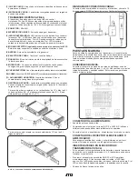
To combine two receivers in a 19" standard rack by using 2 short L type plastic

racks (L2) and 2 metal connecting plates (C1). (Each system includes a L2 and a C1.)

To mount a receiver in a 19" standard rack by using 2 long L type metal

racks (L1).

NOTE: THE UF-8264 RECIEVERS CANNOT BE COMBINED WITH EACH OTHER.

CHARGING CONNECTING DIAGRAM:

Connect the supplied DC cable to the receiver and the microphone, and it takes
around 10 hours to charge and the LED of transmitter is flashing all the time.

Summary of Contents for UF-2064 M

Page 1: ...RATIONS MANUAL BEDIENUNGSHANDBUCH MANUAL DEL OPERADOR MANUEL D INSTRUCTIONS UF I064 M H L UF I264 M H L UF 2064 M H L MH ML UF 8264 M H L PROFESSIONAL UHF MICROPHONE SYSTEMS PROFESSIONELLE UHF MIKROPHON SYSTEME SISTEMASDEFRECUENCIAUHFPROFESIONALESDELMICRÓFONO SYSTÈMESÀFRÉQUENCEUHFPROFESSIONNELSDEMICROPHONE ...

Page 2: ... 2 2 2 2 2 uf SERIES uf SERIES uf SERIES uf SERIES uf SERIES RECEIVERS UF 1064 UF 1264 UF 2064 UF 8264 FM 64 MICROPHONE FB 64 TRANSMITTER ...

Page 3: ...5MHz 807 250MHz 797 375MHz 807 500MHz CHANNEL 4 797 625MHz 807 750MHz 797 875MHz 808 125MHz 798 125MHz 808 500MHz 798 500MHz 808 750MHz CHANNEL 5 798 750MHz 808 875MHz 798 875MHz 809 250MHz 799 250MHz 809 500MHz 799 500MHz 809 750MHz CHANNEL 6 799 875MHz 809 875MHz 800 125MHz 810 125MHz 800 375MHz 810 500MHz 800 625MHz 810 750MHz CHANNEL 7 801 250MHz 811 125MHz 801 500MHz 811 375MHz 801 750MHz 811...

Page 4: ...1064 receiver FB 64 belt pack transmitter with mic line switch LAV X3 lavalier mic with mini XLR UF 1264 M includes UF 1264 diversity receiver FM 64 handheld microphone UF 1264 H includes UF 1264 diversity receiver FB 64 belt pack transmitter with mic line switch HSM X3 headset mic with mini XLR UF 1264 L includes UF 1264 diversity receiver FB 64 belt pack transmitter with mic line switch LAV X3 l...

Page 5: ...med selectable frequencies to avoid interference Various uni directional electret condenser capsule options Use 1 5V x 2 AA size batteries for low operating cost 1 INPUT CONNECTOR Mini XLR microphone connector connect the headset or lavalier here 2 ON OFF SWITCH Turns transmitter power on and off 3 LOW BATTERY LED LED indicates battery status Switching the power to ON the LED flashing once indicat...

Page 6: ...nput AF Response 50Hz to 15KHz 3dB T H D 1 at 1KHz Power Supply DC 12 18V Audio Output Balanced unbalanced output Current Consumption 260mA 10mA Dimension mm WxHxD 210 x 44 x 165 UF 1264 Frequency range USA 790 806MHz Europe a France UK 854 865MHz b Germany 794 813MHz Case Half 19 EIA Case Receiving System PLL synthesized Receiving Mode 64CH Single Channel Switching diversity Frequency Stability 0...

Page 7: ...F Anlagen und den FCC Bestimmungen nach Teil 15 Der Betrieb muß die folgenden beiden Bedingungen erfüllen 1 Diese Anlage darf im Betrieb keine Störungen Interferenzen verursachen und 2 muß beim Empfang Störungen Interferenzen akzeptieren auch solche die einen normalen Betrieb ausschließen Achtung Änderungen und Modifikationen die vom Hersteller nicht erprobt und zugelassen sind führen zum Erlösche...

Page 8: ...m System ein Plastikwinkel L2 und ein Metallverbinder C1 beigelegt Um einen Receiver in ein 19 Rack einzubauen benötigen Sie zwei lange Metallwinkel L1 Die UF 8264 Empfänger können nicht miteinander verbunden werden CHARGING CONNECTING DIAGRAM Verbinden Sie den Sender mit Hilfe des beigefügten DC Kabels mit dem Empfänger und laden Sie den Sender in ca 10 Std auf EINSTELLUNGEN UND BETRIEB Stellen S...

Page 9: ...findlichkeit bei 8dBuV 80dB S N ratio Rückwärtsdämpfung 80dB minimum Kanaltrennung 50dB Modulation FM IF Frequenz 1 56MHz 2 10 7MHz Dynamikbereich 96dB Tonfrequenz 32 768KHz Geräuschabstand 94dB bei 48KHz Bandbreite und 60dB Antenneneingang Audiofrequenzbereich 50Hz bis 15 KHz 3dB T H D 1 bei 1KHz Spannungsversorgung Gleichspannung 12V 18V Audioausgang symmetrische und unsymmetrische Ausgänge Stro...

Page 10: ... causar un mal funcionamiento Nota Los cambios o modificaciones no expresamente aprobadas por la parte responsable del cumplimiento pueden anular la autorización del usuario a utilizar el equipo Nota importante para cumplir con los requerimientos de exposición a RF del FCC no cambie ninguna pieza ni la antena Cualquier cambio de estos elementos puede ocasionar el exceso de exposición a RF anulando...

Page 11: ...mbinar dos receptores en un rack estándar de 19 utilice las 2 L cortas de plástico L2 y 2 platinas metálicas de conexión C1 Cada sistema incluye un juego de L2 y C1 Para montar un solo receptor en un rack estándar de 19 use las 2 L largas de metal L1 NOTA EL UF 8264 NO PUEDE SER COMBINADO CON NINGUN OTRO DIAGRAMA DE CONEXIÓN DE CARGA Conecte el cabe suministrado al receptor y al micrófono y durant...

Page 12: ... 854 865MHz b Germany 794 813MHz Case Half 19 EIA Case Receiving System PLL synthesized Receiving Mode 64CH Single Channel Switching diversity Frequency Stability 0 05 Receiving Sensitivity At 8 dBuV over 80dB S N ratio Image Spurious Rej 80 dB minimum Selectivity 50dB Modulation Mode FM IF Frequency 1st 56MHz 2nd 10 7MHz Dynamic Range 96dB Tone Signal 32 768KHz S N Response Over 94dB at 48KHz dev...

Page 13: ...1 cet ensemble ne doit pas causer d interférences nuisibles et 2 cet ensemble doit tolérer les interférences reçues lors de mauvaise manipulation Remarque toute modification non approuvé par l organisme de régulation peut annuler l autorisation d utilisation de l appareil Important afin de rester en conformité avec la réglementation en vigueur Directive R TTE 1999 5 EC du 5 mars 1999 aucune modifi...

Page 14: ...e LED indique l état des batteries piles Positionnez la touche power sur ON la LED clignote une fois indiquant que les batteries piles de l émetteur sont suffisamment chargées Si la LED reste allumée cela indique que les batteries piles sont faibles et doivent être changées ou rechargées très prochainement Si la LED ne s allume pas cela indique que les batteries piles sont vides et doivent être ch...

Page 15: ...tre installation ne soit pas trop élevé ou trop bas Vérifiez les interférences éventuelles ne viennent pas d autres appareils TV radio CARACTERISTIQUES TECHNIQUES UF 1064 Plage de fréquences USA 790 806MHz Europe a France UK 854 865MHz b Germany 794 813MHz Dimensions 1 2 19 x 1U Récepteur Circuit boucle à verrouillage de phase PLL Mode de réception 64 Fréquences Mono canal Non diversity Stabilité ...

Page 16: ... form or by any means electronic electrical mechanical optical chemical including photocopying and recording for any purpose without the express written permission of Gemini Sound Products Corp It is recommended that all maintenance and service on this product is performed by Gemini Sound Products Corp or its authorized agents Gemini Sound Products Corp will not accept liability for loss or damage...

Reviews: