


- 13 -
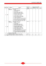
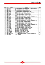
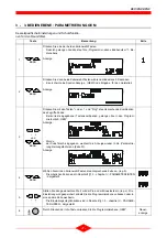
IV - PARAMETER LIST
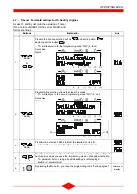
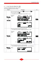
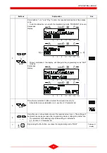
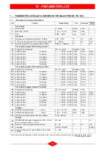
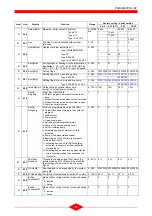
1 - PARAMETER LIST QAA73 (STORED IN THE QAA73 FROM 1 TO 199)
1.1 - Overview of end-user parameters
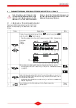
* These lines are only displayed in OpenTherm Plus mode. Also, the relevant functions must be supported by boiler control.
- - : - -
= Switching point inaktiv
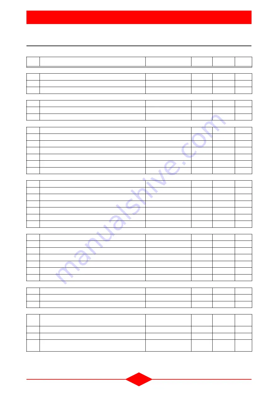
Line
Function
Range/display
Unit
Resolution
Factory
setting
Time of day
1
Time of day
0...23:59
hh:mn
1 min
-
2
Date (day, month)
1. jan ... 31 dec
tt:mm
1 day
-
3
Year
2000 ... 2094
yyyy
1 year
-
Set points
5
Reduced room temperature setpoint (TRRw)
TRF ... TRN
°C
0.5
16.0
6
Frost protection setpoint of room temperature (TRF)
4 ... TRRw
°C
0.5
10.0
7*
Nominal setpoint of d.h.w. temperature (TBWw)
TBWR ... TBWmax
°C
1
60
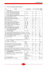
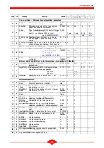
Time switch program HC1 (heating circuit 1)
10
Preselection of weekday
Mo...Su, week
Weekday 1 day
-
11
switch-on time
1st phase
- - : - - / 00:00 ... 24:00 hh:mn
10 min
06:00
12
switch-off time
1st phase
- - : - - / 00:00 ... 24:00 hh:mn
10 min
22:00
13
switch-on time
2nd phase
- - : - - / 00:00 ... 24:00 hh:mn
10 min
--:--
14
switch-off time
2nd phase
- - : - - / 00:00 ... 24:00 hh:mn
10 min
--:--
15
switch-on time
3rd phase
- - : - - / 00:00 ... 24:00 hh:mn
10 min
--:--
16
switch-off time
3rd phase
- - : - - / 00:00 ... 24:00 hh:mn
10 min
--:--
Time switch program HC2 (heating circuit 2)
20*
Preselection of weekday
Mo...Su, week
Weekday 1 day
-
21*
switch-on time
1st phase
- - : - - / 00:00 ... 24:00 hh:mn
10 min
06:00
22*
switch-off time
1st phase
- - : - - / 00:00 ... 24:00 hh:mn
10 min
22:00
23*
switch-on time
2nd phase
- - : - - / 00:00 ... 24:00 hh:mn
10 min
--:--
24*
switch-off time
2nd phase
- - : - - / 00:00 ... 24:00 hh:mn
10 min
--:--
25*
switch-on time
3rd phase
- - : - - / 00:00 ... 24:00 hh:mn
10 min
--:--
26*
switch-off time
3rd phase
- - : - - / 00:00 ... 24:00 hh:mn
10 min
--:--
Time switch program domestic hot water
30
Preselection of weekday
Mo...Su, week
Wekday
1 day
-
31
switch-on time
1st phase
- - : - - / 00:00 ... 24:00 hh:mn
10 min
06:00
32
switch-off time
1st phase
- - : - - / 00:00 ... 24:00 hh:mn
10 min
22:00
33
switch-on time
2nd phase
- - : - - / 00:00 ... 24:00 hh:mn
10 min
--:--
34
switch-off time
2nd phase
- - : - - / 00:00 ... 24:00 hh:mn
10 min
--:--
35
switch-on time
3rd phase
- - : - - / 00:00 ... 24:00 hh:mn
10 min
--:--
36
switch-off time
3rd phase
- - : - - / 00:00 ... 24:00 hh:mn
10 min
--:--
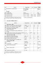
Holidays
40
Holidays start (day.month)
- - : - - = inactif
1. jan ... 31 dec
tt.mm
1 day
- - : - -
41
Holidays end (day.month)
- - : - - = inactif
1. jan ... 31 dec
tt.mm
1 day
- - : - -
42
Heating circuit operating level during holidays
Frost, reduced
-
-
Frost
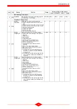
General
45
STANDARD time switch programs for HC1 + 2 and
d.h.w.
(press both buttons -/+ for 3 s)
No, yes
-
-
no
46
Summer / winter changeover temperature
8 ... 30
°C
0.5
19.0
47
Language German,
English
-
-
English
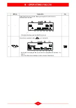
50*
Display of fault (error code of QAA73.110 or boiler
control)
0 ... 255
-
1
-


