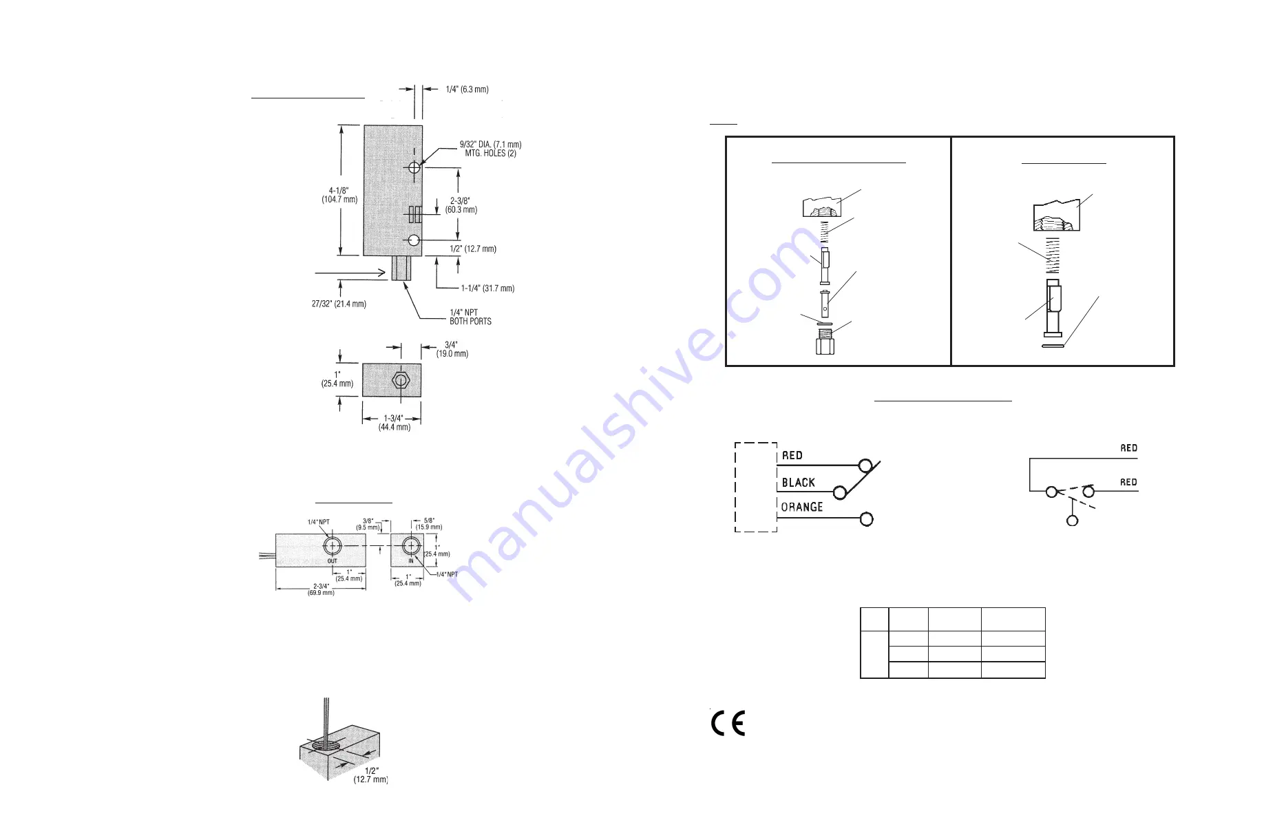
Dimensions . . .
This product is suitable for Class I and Class II applications only, per the requirements of standard EN60730 and any
additional specific requirements for a particular application or medium being sensed. Class I compliance of metal
bodied units requires a ground connection between the metal body and the earthing system of the installation. Class
I compliance of plastic bodied units in contact with a conductive medium requires that the medium be effectively
earthed so as to provide an earthed barrier between the unit and accessible areas. For Class III compliance, a supply
at safety extra-low voltage (SELV) must be provided. Please consult the Factory for compliance information on
specific part numbers.
Switch Ratings
Max. Resistive Load
VA
20
Volts
0-30
120
240
Amps DC
.3
.13
.06
Amps AC
.4
.17
.08
Typical Wiring Diagrams
FS-927 Series
FS-925, FS-926, FS-930 Series
A
C
B
Pin Connections for
Units with MS Receptacle
FS-925/926/930 Series
Piston
Inlet
Fitting
Housing
Spring
Low Flow Piston
(FS-926 ONLY)
O-Ring
FS-927 Series
Housing
Spring
Retainer
Ring
Piston
Accumulation of foreign debris should periodically be removed from these switches. Occasional "wipe-
down" cleaning when excessive contamination is present is all that is normally required. To clean: Remove
unit from system and disassemble as shown below. Clean all parts, reassemble and reinstall unit.
Note:
50 micron filtration is recommended.
Maintenance . . .
FS-927 Series
Electrical Connection
(1/2" NPT Conduit)
(FS-925/FS-930)
(FS-926) 1-9/32" (32.5mm)
FS-925/926/930 Series
For FS-926 the inlet fitting it torqued at the factory. Hold
fitting hex with wrench at installation to prevent additional
accumulation torque which could cause sensor malfunction.


