background image


Genebre Building. Av. de Joan Carles I, 46-48 
08908 L'Hospitalet de Llobregat. Barcelona (Spain) 
genebre@genebre.es   - www.genebre.es 


GENEBRE S.A. 

UPDATE DATE: 07/07/2020              UPDATE NUMBER:  1 


10 

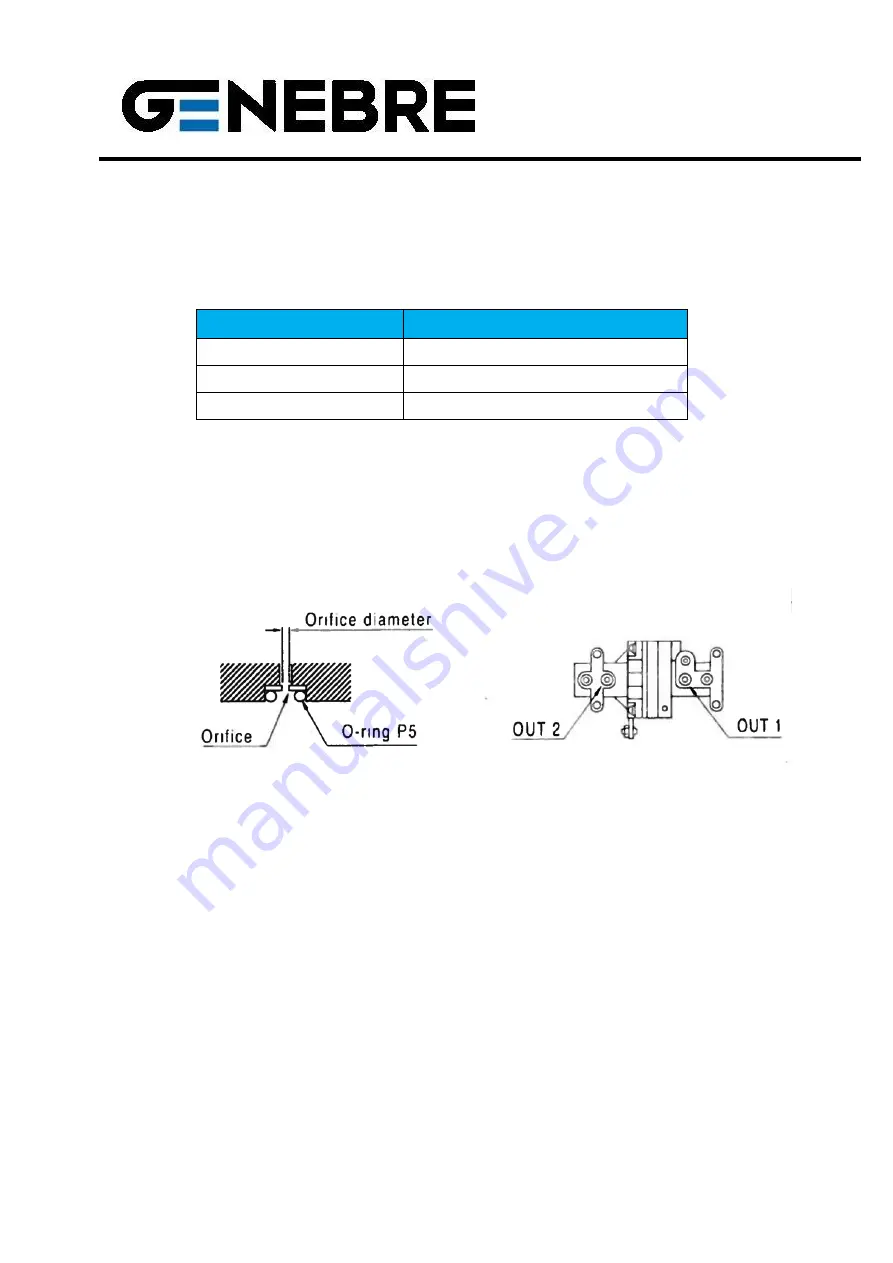
8.5 Air throttle in pilot valve 

 
In case of low air capacity actuators, there could be oscillation in the equipment, 
rendering it inoperative. In such a case, use air throttles in outputs OUT1 and OUT2 of 
the pilot valve. There are two available measures that come with the equipment: 


Actuator Volume 

Output Orifice Diameter 

Smaller than 90 cm

Ø  0,7 

Between 90 ~ 180 cm

Ø  1,0 

Bigger than 180 cm

None 


  Remove the pilot valve. 

  Remove the o-ring, place the throttle and insert the o-ring again. Be careful not to 

leave any foreign bodies in the orifice of the throttle. 

  Perform the same operation on both air outputs (OUT 1 and OUT 2). 

  Replace the pilot valve. 


If the oscillation persists after performing this operation, please contact Genebre S.A. 


9. Maintenance 


Even though this equipment requires no maintenance, it is recommended to carry out 
regular inspections, which must include: 
 

  Verifying the mounting / alignment of the actuator and the positioner. 

  Verifying the electrical connection of the signal. 

  Making sure all bolts are present and tightened. 

  Verifying the state of the filters of the air installation to ensure that good quality air 

reaches the equipment. 


Summary of Contents for 5950 00

Page 1: ...08 L Hospitalet de Llobregat Barcelona Spain genebre genebre es www genebre es GENEBRE S A UPDATE DATE 07 07 2020 UPDATE NUMBER 1 1 INSTALLATION OPERATION AND MAINTENANCE MANUAL Pneumatic Positioner f...

Page 2: ...eatures 3 3 Security Instructions 3 4 Transport and Storage Conditions 4 5 Preliminary Checks 4 6 Positioner Installation 5 6 1 Installation of the Support and the Positioner on the actuator 5 6 2 Mou...

Page 3: ...nd Technical Features Description Values Input signal 3 15 psi 0 2 1 bar Supply pressure 1 4 7 bar 20 100psi Stroke 0 90 Air connection G 1 4 Gauge connection G 1 8 Protection IP66 Ambient temperature...

Page 4: ...ses Genebre S A recommends to visually examine the possible damages suffered during transportation and storage Visual inspection must include the interior of compartments 5 Preliminary Checks Verify t...

Page 5: ...of the positioner s output shaft and the main shaft of the rotating actuator are concentric Type C connection see figure is Namur direct connection to the actuator The positioner s support is designed...

Page 6: ...over of the positioner Remove the clamping screw from the indicator plate and remove the plate Remove the clamping nut from the cam Remove the cam and turn with the side marked as DA facing up Mount t...

Page 7: ...egulator with a filter to constantly maintain the supply air pressure optimum supply pressure of 6 bar to operate the actuator 2 Purge the air circuit completely to avoid strange particles 3 In applic...

Page 8: ...RO setting wheel clockwise or counter clockwise until the reference lines of the indicator cam and the tangent point of the bearing match ZERO In the case of the single effect actuator check that it i...

Page 9: ...not apply to the single effect actuator connected to output OUT2 8 4 Seat Adjustment In case of very low sensitivity due to the actuator working at its maximum load limit turn the Seat Adjuster clock...

Page 10: ...cm3 None Remove the pilot valve Remove the o ring place the throttle and insert the o ring again Be careful not to leave any foreign bodies in the orifice of the throttle Perform the same operation o...

Page 11: ...r flow hole located on the A M regulator to remove any particles that might be left inside Cleaning the A M Switch Finally clean the A M Switch regulator using air and place it back in the enclosure D...

Reviews: