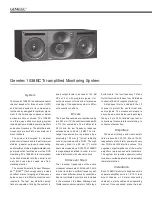
speak er in its required lis ten ing po si tion,
tak ing note of the line of the listening axis
(see figure 1) and install the amplifier
into a standard 19" rack. Sufficient cool-
ing for the amplifier must be ensured. The
minimum clearance for the amplifier is 10
centimeters (4”) to any object. The space
adjacent to the amplifier must either be
ventilated or sufficiently large to dissipate
heat so that the ambient temperature does
not rise above 35 degrees Celsius (95°F).
When flush-mounting the units it should
be noted that the ca ble con nec tors re quire
10 cm (4") of free space behind both the
speak er and the amplifier.
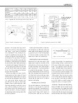
Before con nect ing up, en sure that the
mains switch is off (see figure 2). Check
that the mains volt age se lec tor is cor rect ly
set and that the ap pro pri ate fuse is fitted.
The connecting cables between the
am pli fi er and the speak er cabinet have
Speakon 8- and 4-pole connectors. Push
the 4-pole con nec tor in and turn it clock-
wise until the re tain ing clip clicks. The 8-
pole (thick er) type is con nect ed by push-
ing the con nec tor in, turn ing it clock wise
and tight en ing the blue locking collar at the
end of the connector.
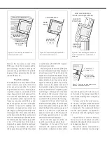
Audio in put to the am pli fi er is made via a
10k Ohm bal anced (XLR) lead, but un bal -
anced leads may be used as long as pin 3
is grounded to pin 1 of the XLR (see figure
3). Once con nec tion has been made, the
speak ers are ready to be pow ered-up.
Setting the input sensitivity
Adjustment of the input sen si tiv i ty of each
speaker can be made to match that of the
mixing desk or other sourc es, by use of
the input sen si tiv i ty control on the amplifier
panel (see figure 2). A small screwdriver
is needed for the ad just ment. The man u -
fac tur er default set ting for this con trol is -6
dBu (fully clockwise) which gives an SPL
of 100 dB @1m with -6 dBu input level.
Note that to get the full output level of
120 dB SPL, an input level of +14 dBu is
needed at this set ting.
Setting tone controls
The acoustic response of the sys tem may
also have to be adjusted to match the
acoustic environment. The ad just ment is
done by setting the five tone control switch
groups 'bass tilt', 'bass roll-off', 'bass level',
'mid level' and 'treble level' on the rear
panel of the amplifier. The man u fac tur ers
de fault set tings for these controls are 'All
Off' to give a flat anechoic re sponse. See
Table 1 for sug gest ed tone control set-
tings in dif fer ing acous tic en vi ron ments.
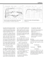
Fig ure 8 shows the effect of the controls
on the anechoic response. Al ways start
ad just ment by setting all switch es to the
'OFF' po si tion. Then set only one switch
to the 'ON' position to select the re sponse
curve required. If more than one switch is
set to 'ON' (within one switch group) the
at ten u a tion value is no longer accurate.
Vertical / horizontal mounting
Genelec 1038BC can be mounted vertical
ly or hor i zon tally. If the speakers orienta-
tion is changed the DCW plate must be
ro tat ed so that the mid-range driv er al ways
re mains lo cat ed at the bot tom of the DCW.
Figure 2. Amplifier panel layout of the 1038BC
Figure1. Location of the acoustic axis
Table 1. Suggested tone control settings in some typical situations
Figure 3. RCA to XLR cable
Speaker mounting
position
Bass
roll-off
Bass
tilt
Bass
level
Midrange
level
Treble
level
Free field anechoic
response
None
None
None
None
None
In a corner
-2 dB
-2 dB
-2 dB
None
None
Soffit mounted in a
control room wall
None
None
-4 dB
None
None
CAL POSITION
ALL TONE CONTROLS : OFF
INPUT SENSITIVITY : -6dBu
LEVEL CONTROLS
20Hz
400Hz
3kHz
20kHz
WARNING
ELECTRIC SHOCK HAZARD!
1038BC TRI-AMPLIFIED MONITORING SYSTEM
NEVER OPERATE THIS EQUIPMENT
WITHOUT A PROPER EARTHED MAINS
CONNECTION. DISCONNECT THE MAINS
INPUT BEFORE REPLACING THE FUSE.
THIS EQUIPMENT IS CAPABLE OF
PRODUCING SOUND PRESSURE LEVELS
IN EXCESS OF 85dB WHICH MAY CAUSE
PERMANENT HEARING DAMAGE.
ENSURE THAT THE CORRECT VOLTAGE
AND APPROPRIATE FUSE ARE SELECTED
BEFORE CONNECTING TO THE MAINS
SUPPLY.
DO NOT EXPOSE TO WATER OR MOISTURE.
IT IS FORBIDDEN TO UNDO ANY SCREWS
ON THIS EQUIPMENT. SERVICING AND
ADJUSTMENT MUST ONLY BE CARRIED
OUT BY QUALIFIED SERVICE PERSONNEL.
GENELECR
SERIAL
NUMBER
f
dB
BASS
0
-1
-2
-3
-4
-5
-6
MAINS
VOLTAGE
SELECTOR
MAINS INPUT
ON
-4
dBu
INPUT SENSITIVITY
SIGNAL INPUT
50 / 60 Hz
500 Watts
115 / 230 V
T6.3A / T3.15A
2
20Hz
100Hz
MADE IN FINLAND
www.genelec.com
-8
-6
+6
1
+4
+2
0
PIN 1 = GROUND
PIN 2 = + INPUT
PIN 3 = - INPUT
MAINS
FUSE
3
-6
INPUT SENSITIVITY
REQUIRED FOR 100dB
SPL@1m. REFER TO
OPERATING MANUAL
FOR MAXIMUM SPL.
-4
-2
OFF
ON
OFF
ON
OFF
ON
OFF
ON
20Hz
250Hz
-6
0
-2
dB
-8
ALL OFF
0
-2
dB
-4
ALL OFF
MID
TREBLE
BASS
TILT
BASS
ROLL-OFF
-2
-4 dB
-6
-8
-2
-4 dB
-6
-8
BASS
LEVEL
-1
-2
-3
-4 dB
-5
-6
MUTE
MID
LEVEL
-1
-2
-3
-4 dB
-5
-6
MUTE
REFER TO THE OPERATING MANUAL FOR
SUGGESTED TONE CONTROL SETTINGS.
USING THE TONE CONTROLS
FOR A FLAT FREE FIELD RESPONSE SET ALL
TONE CONTROLS TO OFF.
FOR ACCURATE OPERATION ONLY ONE
SWITCH IN EACH TONE CONTROL GROUP
SHOULD BE ON AT A TIME.
OFF
ON
-1
-2
-3
-4 dB
-5
-6
MUTE
TREBLE
LEVEL
INPUT
SENSITIVITY
CONTROL
MAINS VOLTAGE
SELECTOR
MAINS SWITCH
BASS TILT
CONTROL
BASS ROLL-OFF
CONTROL
SIGNAL INPUT
CONNECTOR
MAINS FUSE
MAINS INPUT
CONNECTOR
TREBLE, MIDRANGE
AND BASS LEVEL
CONTROLS
GENELEC
>
1
m
500 mm
(19 3/4 )
″
h2
h2=
GENELEC
>
1
m
950 mm (37 3/8 )
″
350 mm
(13 3/4 )
″
453 mm
(17 7/8 )
″
200 mm
(7 7/8 )
″
h1
h1=


