background image

Subwoofer Positioning

1

2

2

3

3

4

'Soffit' Mount

5

The figure to the left shows some example subwoofer positions
within a room. Unless mentioned otherwise, the vents of the
subwoofer should face towards the nearest wall.

1

Recommended position.

2 & 3

Recommended only when using two subwoofers.

4

This arrangement may cause a loss in low
frequencies if the distance from the listening position
to the front wall is between 1 and 3m.

5

The 'Soffit' or flush mount is also recommended.
Here the vents must radiate into the room.

Safety Considerations

The 1094A/92A has been designed in
accordance with international safety
standards. However, to ensure safe
operation and maintain the instrument
under safe operating conditions the
following warnings and cautions should
be observed.

-

Servicing and adjustment should
only be performed by qualified
service personnel.

-

Opening the amplifier's rear panel
is strictly prohibited except by
such persons who  are aware of the
hazards involved.

-

It is forbidden to use this product
with an unearthed mains cable,
which may lead to personal injury.

Warning!

This equipment is capable of delivering
sound pressure levels in excess of
85dB, which may cause permanent
hearing damage.

Overload Indicators

The 1094A contains a red 'Clip'  LED.
This indicator is located on the rear
panel of the subwoofer.
The clip LED will light if the amplifier
is overloaded. If this occurs frequently,
reduce the input level to the subwoofer
until the clip LED stops blinking.

Positioning in the Room

The placement of the subwoofer in the
room will affect the overall frequency
response of the system as, with low
frequencies, the effects of the room
are more apparent.

The subwoofer radiation ports should
be placed within 1m of a wall. The
amplifier panel should not be positioned
less than 10 cm from a surface, as this
may cause heat dissipation problems
from the amplifier back plate. The
placement will affect the phase
difference between the main monitors
and the subwoofer, and also the bass
roll-off rate. These effects can be
compensated by the use of the controls
in the amplifier unit; but consideration
should be made when placing the
subwoofer.

Choose a central and symmetrical
position for the subwoofer as this will
give an even phase match between all
monitor channels. Positioning the
subwoofer close to a corner should be
avoided as it will boost the bass level
at lower frequencies and may cause
asymmetrical spatial imaging.

See the section titled 'Subwoofer
Positioning' for examples of
recommended positions within a room.

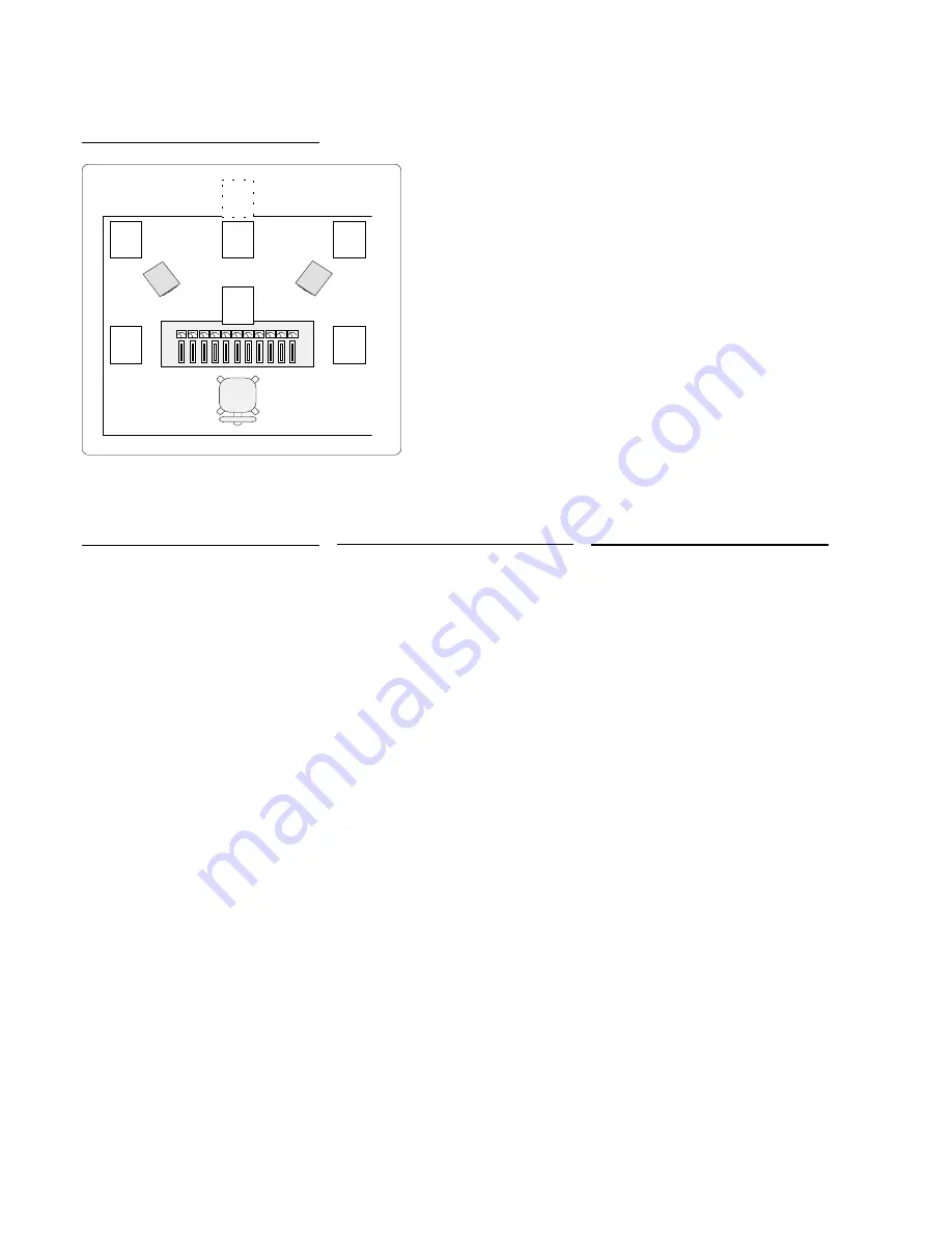
Figure 2. Subwoofer positioning

Summary of Contents for 1092A

Page 1: ...Manual Manual Manual Genelec 1094A and 1092A Genelec 1094A and 1092A Genelec 1094A and 1092A Genelec 1094A and 1092A Genelec 1094A and 1092A Active Subwoofer Systems Active Subwoofer Systems Active Subwoofer Systems Active Subwoofer Systems Active Subwoofer Systems ...

Page 2: ...ils see the Positioning section Before connecting the audio signals ensure that both the subwoofer and the main monitors are switched off Check that the subwoofer voltage selector switch is set to the correct voltage and that the correct fuse for that voltage is fitted Audio connections to the subwoofer are made via balanced XLR connectors Signals from the source are fed into the subwoofer input c...

Page 3: ...cause permanent hearing damage Overload Indicators The 1094A contains a red Clip LED This indicator is located on the rear panel of the subwoofer The clip LED will light if the amplifier isoverloaded Ifthisoccursfrequently reducetheinputleveltothesubwoofer until the clip LED stops blinking Positioning in the Room Theplacementofthesubwooferinthe room will affect the overall frequency response of th...

Page 4: ...se D ifference 18 0 P hase D ifference 27 0 85 Hz 85 Hz 85 Hz 85 Hz Setting the Phase Control Theeffectofincorrectphasealignment betweenmainmonitorsandsubwoofer is a drop in the frequency response of the whole system at the crossover frequency The graphs below figure 3 show the effect of phase difference on the frequency response The phase difference between the main monitors and subwoofer at the ...

Page 5: ...tereo mode To combine the subwoofers into the system so that they produce mono sub bass signals connect the system as shown to the left Note that the level generated by the subwoofers will be 6dB greater than that generated by a single subwoofer hence reduce the sensitivity control of each subwoofer by 6dBu so that the level balance is maintained between the subwoofer and the main monitors beofthe...

Page 6: ... within the decoder will effect the performance of the subwoofer Subwoofer in Digital Discrete 5 1 Surround Sound systems Digital decoders for example Dolby Digital Surround AC 3 DTS and DMAG2 have a discrete subwoofer channel output which should be connected to the sub input on the 1092Aor1094A seefigure10above Thisenablesthesubwoofertocorrectly reproduceallthesub bassinformation in the mix Genel...

Page 7: ... centre monitor can be made from either one of the subwoofer centre channels outputs Notethatasabovethelevelsensitivity is 6dBu different from the single subwoofer system shown in figures 9 and 10 Guarantee This product is supplied with a ONE yearguaranteeagainstmanufacturing faults or defects that might alter the performanceofthe1094A 1092Aunit Refer to supplier for full sales and guarantee terms...

Page 8: ...b www genelec com www genelec com www genelec com www genelec com www genelec com E mail E mail E mail E mail E mail genelec genelec com genelec genelec com genelec genelec com genelec genelec com genelec genelec com Short term amplifier output power 400 W 8 Ohm 180 W 4 Ohm Long term output power is limited by driver unit protection circuitry Amplifier system distortion at nominal output THD 0 08 ...

Reviews: