>110 cm (43 in
)
Main
monitor
< 60 cm (24 in
)
Figure 3. Recommended distances to
the front wall
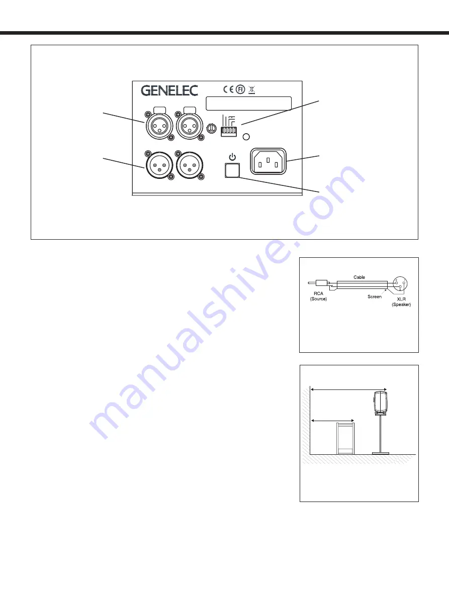
Figure 1. 7040A's amplifier panel, connectors and controls.
Figure 2. XLR to RCA connector for
connecting to an unbalanced signal source.
Audio connections to the subwoofer
and monitors use balanced XLR cables
(not included in the subwoofer delivery
content). As the 7040A has an integrated
amplifier, it may only be connected to a
line level signal source, such as a mixing
console or preamplifier, never to the loud-
speaker outputs of a power amplifier or an
integrated amplifier.
The source is connected to the "LEFT
IN" and "RIGHT IN" connectors of the
subwoofer. The subwoofer’s output con-
nectors "LEFT OUT" and "RIGHT OUT" are
connected to the monitors.
If the signal source has unbalanced
RCA outputs, you can use signal cables as
shown in Figure 2.
Once all connections have been made, the
subwoofer and monitors can be powered up.
Positioning In The Room
Placement of the subwoofer in the room
affects the subwoofer frequency response
and sound level dramatically, as the room
influences the low frequencies strongly.
Even a slight change in the subwoofer's
location can make a marked difference in
the frequency balance. Often patient and
methodical experimentation is needed to
find the optimum placement. The placement
will also affect the phase alignment between
the monitors and the subwoofer, as well as
the need for bass roll-off adjustment.
First, place the subwoofer slightly offset
from the center of the front wall. The dis-
tance to the nearest wall should be less
than 0.6 m (24 in) measured from the sub-
woofer's driver. This position increases
acoustic loading and sound output due to
the proximity of the wall and floor. Too large
a distance from the wall can cause cancel-
lations and reduce subwoofer output. The
monitor should be placed at least 1.1 m (43
in) away from walls to avoid reduction of
low frequency output (see Figure 3).
If the subwoofer frequency response does
not seem balanced, move the subwoofer
slightly to the left or right. This changes
how the room modes are excited and can
result in improved flatness. Positioning the
subwoofer close to a corner boosts the
subwoofer output but may cause asymmet-
rical spatial imaging at low frequencies.
Operating Environment
The 7040A subwoofer is designed for
indoor use only. The ambient temperature
should be 15-35 °C (50-95 °F) and the rel-
ative humidity 20-80 %. Condensation is
not allowed. If it has been stored or trans-
ported in a cool environment, the product
must be allowed to warm up in its packing
to the ambient temperature before con-
necting mains power.
Sufficient amplifier cooling and reflex
port functioning is required when the
MADE IN FINLAND
www.genelec.com
7040A ACTIVE SUBWOOFER
MAGNETICALLY SHIELDED
SERIAL
NUMBER
LEFT OUT
LEFT IN
RIGHT OUT
RIGHT IN
POWER
ON
ROLL-OFF
-180°
-90°
-4 dB
-2 dB
-270°
ISS-DISABLE
MAINS INPUT
50 / 60 Hz 70 W
100 - 240 V~
-6
0
+6
+3
+12
-3
-4
dBu
SENSITIVITY
FOR 100 dB
SPL @ 1m
SIGNAL INPUT
CONNECTORS
SIGNAL OUTPUT
CONNECTORS
BASS ROLL-OFF
PHASE AND
ISS DISABLE SWITCHES
MAINS INPUT
POWER SWITCH


