background image

6

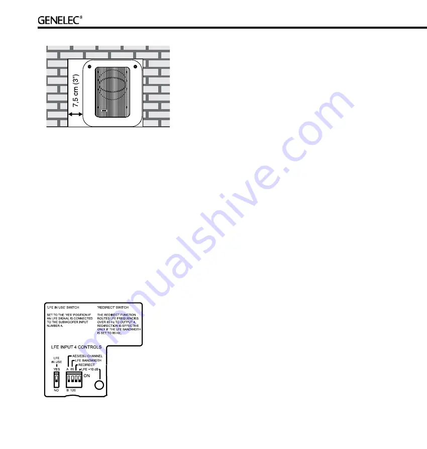
into  the  right  end  of  the  recess  with  the  driver  side  facing  the 
room. This leaves sufficient 7,5 centimeters (") of free space on 
the reflex port side. The height and depth of the recess should 
not be any bigger than those needed to fit the subwoofer flush 
with the wall surface. 

SE7261A Subwoofer Features

Various controls and switches are accessible on the connector 
panel. Let us define and explain here their use and function (from 
left to right):

LFE Input 4 Controls

LFE in Use

When  producing  audio  content  in  multichannel  audio  formats, 
the use of the LFE channel is directly linked to the media release 
format  and  the  type  of  production.  If  in  use,  the  LFE  or  (.1) 

channel must be connected to AES/EBU INPUT 4 and the ‘LFE 
IN USE’ switch must be set to YES position. If no LFE signal is 
used, the ‘LFE IN USE’ switch should be set to NO position. The 
LFE input (AES/EBU INPUT 4) then operates in the same way 
as the other inputs. 

AES/EBU Channel

An  AES/EBU  Single  Wire  signal  normally  carries  two  audio 
channels in what are called subframes A and B. The “AES/EBU 
CHANNEL”  switch  selects  if  the  LFE  signal  is  designated  to 
subframe A or B. 

LFE Bandwidth

The LFE input can be set to two frequency ranges: 19 to 85 Hz 
or  19  to  120  Hz  using  the  “LFE  BANDWIDTH”  switch.  Signal 
content  in  the  LFE  signal  above  the  frequency  value  selected 
on the “LFE BANDWIDTH” switch is either not reproduced or is 
redirected (see below). See also “Typical applications of different 
LFE bandwidth settings” below.

Redirect

Using redirection allows the LFE channel to be monitored as a 
full-bandwidth audio channel. If the LFE signal includes content 
higher  than  120  Hz,  it  can  be  monitored  using  the  “Redirect” 
function. This function allows rerouting of LFE signal above 85 
Hz to the front center loudspeaker. This rerouted LFE content is 
known as the redirected LFE signal.

Setting the “REDIRECT” switch to the “ON” position activates 

the  redirect  function  and  it  can  only  be  activated  if  the  “LFE 
BANDWIDTH” switch is set to “85”.

The  redirected  LFE  signal  is  added  to  the  audio  signal 

contained  in  the  other  subframe  of  the  AES/EBU  audio  cable 
connected to INPUT 4. Typically the LFE channel is paired with 
the Front Center channel, so one of the subframes of OUTPUT 
4  carries  the  sum  of  the  redirected  LFE  signal  and  the  center 
channel  signal.  OUTPUT  4  should  then  be  connected  to  the 
Front Center loudspeaker.

LFE +10 dB

In Dolby Digital and DTS encoding formats the LFE channel is 
monitored with +10 dB gain relative to the main channels. The 
object  is  to  increase  the  headroom  in  the  recorded  signals. 
Surround sound decoders may automatically add +10 dB of LFE 
gain to restore the level balance.

Summary of Contents for SE7261A

Page 1: ...SE7261A DSP Subwoofer Operating Manual ...

Page 2: ... ...

Page 3: ...armful interference to radio communications However there is no guarantee that interference will not occur in a particular installation If this equipment does cause harmful interference to radio or television reception which can be determined by turning the equipment off and on the user is encouraged to try to correct the interference by one or more of the following measures Reorient or relocate t...

Page 4: ...r making the connections and roll the subwoofer back to its normal upright position before use Connections Audio connections Audio connections to the subwoofer are made by XLR connectors All audio cabling from the source must always go first to the input connectors of the subwoofer and then on to the main loudspeakers from the subwoofer s output connectors Connect the digital audio signal cables f...

Page 5: ...driver This position gives increased acoustic loading and SPL due to the proximity of the front wall and floor Cancellations from the front wall and floor are also avoided Front wall cancellation for the 85 Hz high pass filtered main loudspeakers can be eliminated by placing them at least 110 cm 43 away from the front wall In a multichannel system the main loudspeakers should ideally be positioned...

Page 6: ...sing the LFE BANDWIDTH switch Signal content in the LFE signal above the frequency value selected on the LFE BANDWIDTH switch is either not reproduced or is redirected see below See also Typical applications of different LFE bandwidth settings below Redirect Using redirection allows the LFE channel to be monitored as a full bandwidth audio channel If the LFE signal includes content higher than 120...

Page 7: ... bypass function The red BYPASS light is illuminated when the bypass mode is active With the bypass mode on the high pass filters for the loudspeakers are disabled and the system behaves as if the subwoofer was not connected The bypass function has no effect on the LFE signal If there is no LFE signal the subwoofer will not reproduce any signal when the bypass is active Controls selection The subw...

Page 8: ...n be done Disconnect all loudspeakers from the subwoofer outputs Select the loudspeaker to be used as the reference for the phase alignment Typically this is the Front Center loudspeaker in a 5 1 multi channel system Connect this loudspeaker to subwoofer s AES EBU OUTPUT 1 connector Select subframe A for reproduction on the reference loudspeaker The test tone is played simultaneously from the subw...

Page 9: ...ady modest ensure that there are no bit errors in the AES EBU digital audio data Typical applications of different LFE bandwidth settings Using the 85 Hz LFE bandwidth setting with Redirect function is the most universal configuration for LFE monitoring However there are situations when the band limited LFE settings serve a definite purpose Limiting the LFE bandwidth to 85 Hz without using the Red...

Page 10: ...d the subwoofer is necessary to maintain sufficient cooling Do not obstruct airflow around the subwoofer WARNING Genelec SE7261A subwoofer is capable of producing sound pressure levels in excess of 85 dB which may cause permanent hearing damage Guarantee Genelec SE7261A subwoofer is supplied with a two year guarantee against manufacturing faults or defects that might alter the performance of the s...

Page 11: ...0 Hz Maximum short term sine wave SPL output averaged from 30 to 85 Hz measured in half space at 1 meter 108 dB SPL Maximum peak SPL output with random pink noise measured in half space 1 meter 113 dB SPL Self generated noise level in free field 1 m A weighted 15 dB Harmonic distortion 1 m in half space 90 dB SPL 30 to 85 Hz 2nd 3rd 3 2 Driver magnetically shielded 250 mm 10 Weight 27 kg 58 lbs Di...

Page 12: ...Designed to Adapt 750 SE7261A Genelec Document D0082R002 Copyright Genelec Oy 12 2007 All data subject to change ...

Reviews: