iSXblue/SXBlue II GNSS Series Technical Reference Manual
x
List of Figures
Figure 1-2 Package Contents ................................................................................................................................................. 1
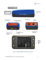
Figure 1-3 iSXBlue/SXBlue II GNSS Main Components .................................................................................................... 3
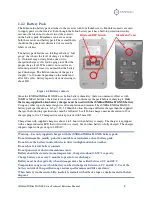
Figure 1-4 Battery contacts .................................................................................................................................................... 4
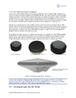
Figure 1-5 Precision and Survey Antennae........................................................................................................................... 5
Figure 1-6 Carrying Case ......................................................................................................................................................28
Figure 1-7 Removing the Magnet Adaptor ..........................................................................................................................29
Figure 1-8 Using the Softhat .................................................................................................................................................29
Figure 1-10 Using the L-Shaped Bracket .............................................................................................................................30
Figure 1-11 Mounting on a Rangepole .................................................................................................................................31
Figure 1-14 Phase Center – Precision GNSS Antenna (GESXB3GLANT) .......................................................................32
Figure 1-16 iSXBlue/SXBlue II GNSS Front Panel ............................................................................................................33
Figure 2-1 Sample Extrapolated Ionospheric Grids ...........................................................................................................40
Figure 2-2 Auto-Dif Error Drift ...........................................................................................................................................43
Figure 2-3 RS-232 Connector Pin-out ..................................................................................................................................47
Figure 3-1 Sample Config. File .............................................................................................................................................54
Figure B-1 Serial Interface ..................................................................................................................................................149
Figure B-2 RTCM Data Output From Serial Port ............................................................................................................150
Figure B-3 RTCM Data Input to Serial Port .....................................................................................................................151
Figure C-1 WAAS Ground Segment (end of 2007) ...........................................................................................................159
Figure C-2 EGNOS Ground Segment (end of 2007) .........................................................................................................160
Figure C-3 Worldwide SBAS Coverage .............................................................................................................................161
Figure C-4 Worldwide SBAS Ionospheric Coverage ........................................................................................................161
Figure C-5 Broadcast and Extrapolated Ionospheric Correction Map ...........................................................................163

