Operation
17973 G
MLT6SM/K-8SK Operating Manual
21
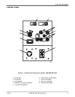
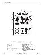
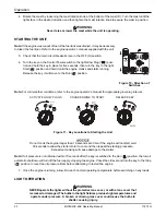
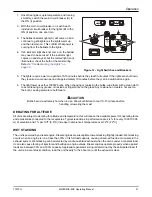
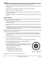
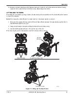
1. Once the engine is up to temperature and running
smoothly, switch the main circuit breaker (A) to
the ON (I) position.
2. With the main circuit breaker on, switch each
individual circuit breaker for the lights (B) to the
ON (I) position, one at a time.
3. The ballast indicator lights (C) will come on and
continue to get brighter as the lights warm up,
and then remain on. This confirms that power is
coming from the ballasts to the lights.
4. If an indicator light does not come on, the ballast
may need to be serviced. If the indicator light
comes on and stays lit, but the related light is not
illuminated, check the bulb or the mast wiring.
Refer to
“Troubleshooting the Lights” on
page 33.
Figure 12 - Light Switches and Breakers
5. The lights require a warm up period of 5-15 minutes before they reach full output. If the lights are shut down,
they require a cool down period of approximately 10 minutes before they can be switched on again.
6. The light tower uses four 1000W bulbs. When checking or replacing the bulbs, wipe them with a clean cloth
to avoid leaving any grease, oil residue or fingerprints on the glass. Any residue can create a hot spot on
the bulb, causing premature bulb failure.
CAUTION
Bulbs become extremely hot when in use. Allow bulb fixture to cool 10-15 minutes before
handling or lowering the mast.
DERATING FOR ALTITUDE
All units are subject to derating for altitude and temperature; this will reduce the available power for operating tools
and accessories connected to the receptacles. Typical reductions in performance are 2-4% for every 1000 ft (305
m) of elevation and 1% per 10ºF (5.6ºC) increase in ambient air temperature over 72ºF (22ºC).
WET STACKING
The unit is powered by a diesel engine. Diesel engines are susceptible to wet stacking if lightly loaded. Wet stacking
occurs when an engine is run at less than 30% of its full load capacity, causing unburned fuel to accumulate in the
exhaust system. Wet stacking can be detected by continuous black exhaust when the unit is under a constant load.
It can also cause fouling of injectors and buildup on engine valves. Diesel engines operate properly when applied
loads are between 30% and 100% capacity. Appropriate generator sizing is determined by the anticipated load. If
the unit is in a wet stack condition, load the unit heavily for five hours or until the exhaust is clear.
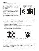
00761
A
I
O
I
O
I
O
I
O
MAIN
BREAKER
240V
I
O
STOP
15 SEC.
MAX.
I
O
12V
DC CIRCUIT
BREAKER
AC CIRCUIT
BREAKERS
120V
B
Summary of Contents for MLT6SK
Page 4: ...iv This Page Intentionally Left Blank ...
Page 12: ...Safety 6 MLT6SM K 8SK Operating Manual 17973 G This Page Intentionally Left Blank ...
Page 32: ...Operation 26 MLT6SM K 8SK Operating Manual 17973 G This Page Intentionally Left Blank ...
Page 34: ...Maintenance 32 MLT6SM K 8SK Operating Manual 17973 G This Page Intentionally Left Blank ...
Page 36: ......

