background image

Generac

®

Power Systems, Inc.

13

TR

GTS

T1

E1

N1

T2

E2

N2

B

1

B2

A2

A1

N1B

N1B

126

E2

E1

N2A

205

N1B

205

E1

E1

A 7

1

B 9

3

6

T1

T

2

N1B

N2A

N3

E3

T3

2

1

8

7

3

4

5

6

126

205

N2A

N2A

N2A

N1B

N1B

N1B

N1B

N1A

N3

PM

N3

N3

N1B

N1B

F2

F1

23

19

4

TS

U

TILITY 2

U

TILITY 1

N2A

N2A

N2A

N3

N3

N3

194

23

23

194

23

194

N1

N2

N2A

N2A

N2A

N2A

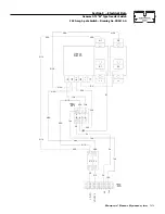
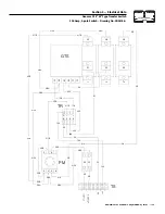
Section 5 — Electrical Data

Generac GTS “W” Type Transfer Switch

200 Amp, 3-pole Switch – Drawing No. 0D3818-A

Summary of Contents for 004635-1

Page 1: ...POWER SYSTEMS INC Owner s Manual GTS W Type Automatic Transfer Switch 200 Amp 250 Volts Model Nos 004635 1 004635 2 This manual should remain with the unit...

Page 2: ...source failure occurs must be isolated from the NORMAL utility power source by means of an approved transfer switch Failure to properly isolate the NORMAL and STANDBY power sources from each other may...

Page 3: ...e standing on metal or concrete place insulative mats over a dry wood platform Work on this equipment only while standing on such insulative mats Never work on this equipment while physically or menta...

Page 4: ...eason codes require it in all standby electric system installations 1 3 TRANSFER SWITCH DATA DECAL A DATA DECAL is permanently affixed to the transfer switch enclosure Use this transfer switch only wi...

Page 5: ...o be connected to it Mount the switch vertically to a rigid supporting structure To prevent switch distortion level all mounting points If necessary use washers behind mounting holes to level the unit...

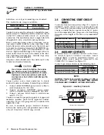
Page 6: ...r LOAD leads to switch termi nals T1 T2 T3 Conductors must be properly supported of approved insulative qualities protected by approved conduit and of the correct wire gauge size in accordance with ap...

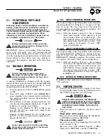
Page 7: ...anually or the manual handle could be damaged 3 2 1 CLOSE TO NORMAL SOURCE SIDE Before proceeding verify the position of the switch by observing window A in Figure 3 1 on page 6 If win dow A reads ON...

Page 8: ...te AC voltmeter and frequency meter check the no load voltage and frequency Single phase generator supply Measure across ATS terminal lugs E1 to E2 E1 to NEUTRAL and E2 to NEUTRAL a Frequency 60 62 Hz...

Page 9: ...er load as follows Turn ON electrical loads to the full rated wattage amperage capacity of the generator DO NOT OVERLOAD With maximum rated load applied check voltage and frequency across transfer swi...

Page 10: ...Systems Inc Section 4 Mounting Dimensions Generac GTS W Type Transfer Switch Mounting Dimensions Drawing No 0D3714 B 180 514 612 490 430 Values are in Millimeters Note Diameter of Mounting holes A is...

Page 11: ...ECTED UTILITY 1 N1 UTILITY 2 N2 LOAD 2 T2 23 194 CB1 NEUTRAL CONNECTION N1 N2 T1 T2 2 T E1 E2 2 E NEUTRAL LUG TRANSFER SWITCH UTILITY SUPPLY WITH SERVICE DISCONNECT LOAD CUSTOMER 194 23 LOAD 2 UTILITY...

Page 12: ...RED LS2 LS3 LS1 T1 T2 2 3 5 6 1 4 C CONTACTOR ACTUATING COIL GTS TRANSFER SWITCH CONTACTOR LS1 LS2 LS3 LIMIT SWITCHES ACTUATOR TR RELAY TRANSFER TS TERMINAL STRIP CUSTOMER CONNECTION N1A F2 N2 N1 F1 N...

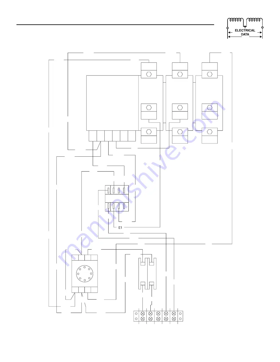
Page 13: ...E2 E1 N2A 205 N1A 205 E1 E1 A 7 1 B 9 3 T1 T2 N1A N2A 126 205 N1A N1A N1A N1A F2 F1 23 194 TS UTILITY 2 UTILITY 1 194 23 23 194 23 194 N1 N2 N2A N2A N2A N2A N2A N2A N1A 23 194 Section 5 Electrical Dat...

Page 14: ...RANSFER SWITCH CONTACTOR LS1 LS2 LS3 LIMIT SWITCHES ACTUATOR PM POWER MONITOR 3 PHASE UTILITY TR RELAY TRANSFER TS TERMINAL STRIP CUSTOMER CONNECTION 3 4 5 N1B N2A N3 PM N1B N1A PM F2 N2 N1 F1 N1B N2A...

Page 15: ...B 9 3 6 T1 T2 N1B N2A N3 E3 T3 2 1 8 7 3 4 5 6 126 205 N2A N2A N2A N1B N1B N1B N1B N1A N3 PM N3 N3 N1B N1B F2 F1 23 194 TS UTILITY 2 UTILITY 1 N2A N2A N2A N3 N3 N3 194 23 23 194 23 194 N1 N2 N2A N2A...

Page 16: ...0C8884 LS 0C7907H S 0C7907H S 0C7907H S A A GROUND LUG ASSEMBLY DETAIL A A ENCLOSURE C8308X C8308X C8308X 0D4545 0A9949 S 0A9949 S 0A9949 T 0A9949 T SUPPLIED W SWITCH HANDLE P N 063321 0A9949 S 0 0 A9...

Page 17: ...2 SCREW TH FRM M6 1X16 N WA Z JS 17 0A1661 2 RIVET POP 156 X 675 AL 18 0C4449A 1 ASS Y NTRL BL150 200A 19 0E2865 1 WELDMENT TRANSFER SWITCH BOX 20 0D3718 1 COVER TRANSFER SWITCH BOX 21 0C8308 2 DECAL...

Page 18: ...2 16 23 27 20 6 35 17 14 12 32 31 38 30 33 Replace with UL listed fuse of same 600 Volt 5 amp type and rating 0D3587 37 NEUT 34 C8308X GROUND LUG ASSEMBLY DETAIL A A 25 9 43 13 10 18 21 13 6 15 14 19...

Page 19: ...X 21 0C8308 2 DECAL TERMINAL SHOCK HAZARD 22 0C2262 1 DECAL TERMINAL STRIP 23 0F6165 2 WASHER M6 NYLON 24 0F5569 1 DECAL SWITCH RATING 25 064101 4 NUT LOCK FL 3 8 16 26 0E2866 1 SUBPLT 200A TS 3R 27 0...

Page 20: ...r to July 1 2004 2 Costs of normal maintenance i e tune ups associated part s adjustments loose leaking clamps installation and start up 3 Any failure caused by contaminated fuels oils coolants antifr...

Reviews: