background image

Maintenance

Owner’s Manual for 60 Hz Air-Cooled Generators

27

7.

(11-22 kW units only): Verify that the air inlet duct
(D) is properly connected to the air cleaner cover.

8.

Press the AUTO button on the control panel to
return the unit to AUTO mode.

Spark Plugs

Proceed as follows to check the spark plug(s) gap and
replace the spark plug(s) as necessary:

1.

With the generator OFF and the engine cool, lift the
lid and remove the front panel.

2.

Clean the area around the base of the spark
plug(s) to keep dirt and debris out of the engine.

3.

Remove the spark plug(s) and check the condition.
Install a new plug(s) if the old plug(s) is worn or if
reuse is questionable. 

4.

Clean the plug(s) by scraping or washing with a
wire brush and commercial solvent. Do not blast
the plug(s) to clean.

5.

Check the spark plug gap using a wire feeler
gauge. Se

Figure 4-6

. Replace the spark plug if

the gap is out of specification. Se

General

Information

.

6.

Reinstall the spark plug(s), and torque to 18.4 ft-lbs
(25 Nm).

7.

Press the control panel AUTO button to return the
unit to AUTO mode.

Figure 4-6. Spark Plug Gap Measurement

Valve Clearance Adjustment

Check the valve clearance after the first 25 hours of
operation, then after 400 hour intervals. Adjust if
necessary.

Important:

 Please contact an IASD for service

assistance. Proper valve clearance is essential for
prolonging the life of the engine.

Check Valve Clearance

NOTE: 

The engine should be cool before checking the

valve clearance. Adjustment is not needed if valve
clearance is within the dimensions provided in

Specifications

.

1.

Close fuel valve and disconnect battery to avoid
accidental start-up.

2.

Remove spark plug wires, and position wires away
from plugs.

3.

Remove spark plugs.

4.

Make sure the piston is at top dead center (TDC) of
its compression stroke (both valves closed). To
move the piston to TDC, remove the intake screen
at the front of the engine to access the flywheel
nut. Use a large socket and socket wrench to
rotate the flywheel nut clockwise, which will rotate
the crankshaft. Watch the piston through the spark
plug hole. The piston should move up and down.
The piston is at TDC when it is at its highest point
of travel.

Adjust Valve Clearance 

See 

Figure 4-7

 or 

Figure 4-8

. Proceed as follows to

adjust the valve clearance:

NOTE: 

Allow engine to cool before adjusting valve

clearance.

1.

Make sure the piston is at top dead center (TDC) of
its compression stroke (both valves closed).

2.

Remove spark plug wire(s) and position wire(s)
away from plugs.

3.

Remove spark plug(s).

4.

Remove the four screws attaching the valve cover.
Remove and discard gasket.

5.

Loosen the rocker jam nut (C) using a 10 mm
wrench (9-11 kW units) or 13 mm wrench (16-22
kW units.)

.

Figure 4-7. Valve Clearance Adjustment (9 kW)

000211

001812

C

D

E

F

Summary of Contents for 20 kW LP

Page 1: ...uct support lookup Pour le fran ais visiter http www generac com service support product support lookup 000918 Register your Generac product at WWW GENERAC COM 1 888 GENERAC 888 436 3722 000209a WARNI...

Page 2: ...nt checked periodically by an IASD Normal maintenance service and replacement of parts are the responsibility of the owner operator and are not considered defects in materials or workmanship within th...

Page 3: ...e Menu Displays 13 The LCD Panel 13 Menu System Navigation 14 Setting the Exercise Timer 16 Battery Charger 16 Manual Transfer Operation 17 Transfer to Generator Power Source 17 Transfer to Utility Po...

Page 4: ...Table of Contents iv Owner s Manual for 60 Hz Air Cooled Generators Section 5 Troubleshooting Quick Reference Guide Generator Troubleshooting 31 Quick Reference Guide 32...

Page 5: ...e manufacturer strongly recommends that if the operator is also the owner to read the owner s manual and thoroughly understand all instructions before using this equipment The manufacturer also strong...

Page 6: ...rm wiring and connections to unit Failure to follow proper installation requirements could result in death serious injury and damage to equipment or property 000115 WARNING Moving Parts Do not wear je...

Page 7: ...ath or serious injury 000150 DANGER Electrocution Never connect this unit to the electrical system of any building unless a licensed electrician has installed an approved transfer switch Failure to do...

Page 8: ...rged or improperly rated fire extinguishers will not extinguish electrical fires in automatic standby generators 000100a WARNING Consult Manual Read and understand manual completely before using produ...

Page 9: ...with Cover E Exhaust Enclosure J Oil Filter N Fuel Regulator B Main Line Circuit Breaker Generator Disconnect F Oil Fill Cap Dipstick K Oil Drain Hose O Fuel Inlet C Control Panel G Status LED Indica...

Page 10: ...Compartment Battery not supplied J Oil Fill Cap N Sediment Trap B Main Line Circuit Breaker Generator Disconnect F Exhaust Enclosure K Oil Filter O Fuel Regulator C Airbox with Air Cleaner G Status L...

Page 11: ...nded When operated above 77 F 25 C there may be a decrease in engine power See Engine These generators are rated in accordance with UL 2200 Safety Standard for Stationary Engine Generator Assemblies a...

Page 12: ...ication The Emission Control System on this generator consists of the following Fuel Requirements The engine has been fitted with a dual fuel carburetion system The unit will run on natural gas or LP...

Page 13: ...bottom of the new air cooled generators This offers a sleek contoured appearance as well as offering protection from rodents and insects by covering the lifting holes located in the base Requires use...

Page 14: ...General Information 10 Owner s Manual for 60 Hz Air Cooled Generators This page intentionally left blank...

Page 15: ...d will be locked A set of keys is attached to the intake side of the generator 1 Cut the plastic bag to remove the keys 2 Use the keys to open the lid of the generator NOTE The enclosed keys provided...

Page 16: ...priately sized padlock not included with a shackle long enough to pass through both lock tabs B Figure 3 3 Main Breaker NOTE DO NOT lock out the MLCB during normal generator operation Doing so will co...

Page 17: ...running under generator power utility is lost OFF This button shuts down the engine and prevents automatic operation of the unit MANUAL This button cranks and starts the generator Transfer to standby...

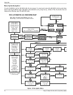
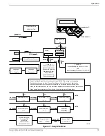
Page 18: ...NG or LP Firmware Update Insert USB Alarm Log Alarm Log Run Log 1 thru 50 1 thru 50 Warning Message s Charger Warning Charger Missing AC Low Battery Battery Problem Exercise Set Error USB Warning Down...

Page 19: ...XXX USB V XXXX Are You Sure Yes or No ESC ENTER ESC ENTER ESC ENTER Select Yes then Press Enter to continue or Press ESCAPE to escape out of updating During update process the Blue Manual light flashe...

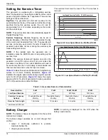
Page 20: ...n the fuse is removed Table 3 1 details the exercise information and programming options for all Home Standby Generators Figure 3 8 illustrates the engine speed profile during a typical exercise cycle...

Page 21: ...load Disconnect transfer switch from all power sources prior to manual transfer Failure to do so will result in death or serious injury and equipment damage 002565 A MANUAL Will not transfer to genera...

Page 22: ...or disconnect to ON CLOSED The generator will start automatically when utility source voltage drops below a preset level Loads are transferred to the standby power source after the unit starts Automat...

Page 23: ...mal genera tor voltage output is determined to be low During this cycle the generator controller will display Warming Up on the display screen The generator controller display will show Under Voltage...

Page 24: ...Operation 20 Owner s Manual for 60 Hz Air Cooled Generators This page intentionally left blank...

Page 25: ...y charger cable Figure 4 1 Disconnecting Battery Charger Cable Performing Scheduled Maintenance It is important to perform maintenance as specified in the Service Schedule for proper generator operati...

Page 26: ...e air filter Clean Check gap Replace spark plugs Inspect adjust valve clearance Inspect clean sediment trap Consult local codes and guidelines Contact the nearest IASD for assistance if necessary Remo...

Page 27: ...he generator to ON CLOSED 4 The system is now operating in automatic mode The main utility disconnect can be turned ON CLOSED Engine Oil Requirements To maintain the product warranty the engine oil sh...

Page 28: ...pter Tighten the filter an additional 3 4 to one full turn 7 Refill the engine with the proper recommended oil See Engine Oil Requirements 8 Press the MANUAL button on the control panel to start the e...

Page 29: ...or service assistance Proper valve clearance is essential for prolonging the life of the engine Check Valve Clearance NOTE The engine should be cool before checking the valve clearance Adjustment is n...

Page 30: ...the Service Schedule Contact an IASD for assistance if necessary Proceed as follows to inspect the battery 1 Press the OFF button to shut down the generator then lift the lid and remove the front pane...

Page 31: ...Sediment Trap The sediment trap removes contaminants moisture and fine particles from gaseous fuels before they enter the fuel regulator Accumulated moisture and particles must be emptied from the sed...

Page 32: ...rankcase with oil 9 Attach a tag to the engine indicating the viscosity and classification of the new oil in the crankcase 10 Remove the spark plug s and spray a fogging agent into the spark plug s th...

Page 33: ...check gap replace plug s as needed 3 Confirm fuel pressure to regulator is 10 12 in water column 19 22 mm Hg for LP and 3 5 7 0 in water column 9 13 mm Hg for natural gas 4 Turn fuel conversion valve...

Page 34: ...ED Unit will not start in AUTO with utility loss Check the LEDs screen for alarms Check oil level and add oil as needed If oil level is correct contact an IASD RPM SENSE LOSS RED Unit will not start i...

Page 35: ...trol panel displays CHECK BATTERY replace the battery BATTERY PROBLEM YELLOW Yellow LED illuminated in any state Check the screen for additional information Contact an IASD CHARGER WARNING YELLOW Yell...

Page 36: ...Troubleshooting Quick Reference Guide 34 Owner s Manual for 60 Hz Air Cooled Generators This page intentionally left blank...

Page 37: ...Troubleshooting Quick Reference Guide Owner s Manual for 60 Hz Air Cooled Generators 35 This page intentionally left blank...

Page 38: ...Troubleshooting Quick Reference Guide 36 Owner s Manual for 60 Hz Air Cooled Generators This page intentionally left blank...

Page 39: ......

Page 40: ...ights reserved Specifications are subject to change without notice No reproduction allowed in any form without prior written consent from Generac Power Systems Inc Generac Power Systems Inc S45 W29290...

Reviews: