background image

Generac Portable Products 3,500 Watt Generator

7

Stopping the Engine

• Unplug all electrical loads from generator panel

receptacles. Never start or stop engine with electrical
devices plugged in and turned on.

• Put the idle control switch in the “Off” position.

• Let engine run at no-load for 30 seconds to stabilize the

internal temperatures of engine and generator.

• Move run/stop switch to “Stop.”

• Close the fuel shut–off valve.

Operating Automatic Idle Control

This switch is designed to greatly improve fuel economy.
When this switch is turned ON, the engine will only
run at its normal high governed engine speed when an
electrical load is connected. When an electrical load is
removed, the engine will run at a reduced speed. With
the switch off
, the engine will run at the normal high
engine speed. Always have the switch off when
starting and stopping the engine.

Charging a Battery

DANGER!

Storage batteries give off explosive

hydrogen gas while recharging. This explosive
mixture will remain around the battery for a long
time after it has been charged. The slightest spark
can ignite the hydrogen and cause an explosion. Such
an explosion can shatter the battery and cause
blindness or other serious injury.

DANGER!

Do Not permit smoking, open flame,

sparks or any other source of heat around a battery.
Wear protective goggles, rubber apron and rubber
gloves when working around a battery. Battery
electrolyte fluid is an extremely caustic sulfuric acid
solution that can cause severe burns. If spill occurs,
flush area with clear water immediately.

Your generator has the capability of recharging a discharged
12 Volt automotive or utility style storage battery. Do Not
use the unit to charge any 6 Volt batteries. Do Not use
the unit to crank an engine having a discharged battery.

To recharge 12 Volt batteries, proceed as follows:

• Check fluid level in all battery cells. If necessary, add

ONLY distilled water to cover separators in battery cells.
Do Not use tap water.

• If the battery is equipped with vent caps, make sure they

are installed and are tight.

• If necessary, clean battery terminals.

• Connect battery charge cable connector plug to panel

receptacle identified by the words “12-VOLT D.C.”

• Connect battery charge cable clamp with red handle to

the positive (+) battery terminal (Figure 5).

• Connect battery charge cable clamp with black handle

to the negative (–) battery terminal (Figure 5).

• Start engine. Let the engine run while battery recharges.

• When battery has charged, shut down engine

NOTE: Use an automotive hydrometer to test battery
state of charge and condition. Follow the hydrometer
manufacturer’s instructions carefully. Generally, a battery is
considered to be at 100% state of charge when specific
gravity of its fluid (as measured by hydrometer) is 1.260 or
higher.

Figure 5 — Battery Connections

Summary of Contents for 3500XL

Page 1: ...blems Questions Before taking your unit back to the store call the generator helpline at 1 800 270 1408 M F 8 5 CT 3500XL This is the safety alert symbol It is used to alert you to potential personal injury hazards Obey all safety messages that follow this symbol to avoid possible injury or death Portable Generator Owner s Manual ...

Page 2: ...e power is not available engine life may be shortened SAFETY RULES This generator set was designed and manufactured for specific applications Do Not attempt to modify the unit or use it for any application it was not designed for If you have any questions about your generator s application ask your dealer distributor or consult the factory The manufacturer could not possibly anticipate every circu...

Page 3: ...arance on all sides of generator even while operating unit outdoors or you could damage the unit Never start or stop the unit with electrical loads connected to receptacles with the connected devices turned ON Start the engine and let it stabilize before connecting any electrical loads Disconnect all electrical loads before shutting down the generator Do Not insert any object through cooling slots...

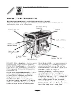
Page 4: ...e push to reset type Fuel Shut Off Valve Controls fuel supply to engine Fuel Tank Capacity of 4 U S gallons Grounding Wing Nut Provides a tie point for connecting the generator frame to earth ground Idle Control Switch The idle control runs the engine at normal high speeds when there is a load present and runs the engine at idle low speeds when a load is not present This feature greatly improves f...

Page 5: ... overfill the fuel tank Always allow room for fuel expansion Use regular UNLEADED gasoline with the Generator engine Do Not use premium gasoline Do Not mix oil with gasoline Clean area around fuel fill cap remove cap Add unleaded regular gasoline slowly to fuel tank Be careful not to overfill Allow about 1 2 of tank space for fuel expansion Figure 2 Install fuel cap and wipe up any spilled gasolin...

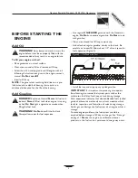
Page 6: ...Shutdown System See engine manual Refer to the engine owner s manual for complete starting instructions Grasp starter grip and pull slowly until you feel slight resistance then pull quickly Ease the starter rope back into the engine When engine starts move choke lever to Run position by sliding it all the way to the right away from the valve cover and under the arrow NOTE If engine fails to start ...

Page 7: ...tery Wear protective goggles rubber apron and rubber gloves when working around a battery Battery electrolyte fluid is an extremely caustic sulfuric acid solution that can cause severe burns If spill occurs flush area with clear water immediately Your generator has the capability of recharging a discharged 12 Volt automotive or utility style storage battery Do Not use the unit to charge any 6 Volt...

Page 8: ...40 F 4 C For a more permanent shelter build a structure that will enclose three sides and the top of the generator Make sure entire muffler side of generator is exposed A typical shelter is shown in Figure 6 Ensure a minimum of two feet clearance between open side of box and nearest object Face exposed end away from wind and elements Enclosure should hold enough heat created by the generator to pr...

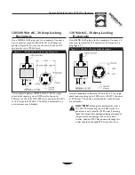
Page 9: ...ocking Receptacle Use a NEMA L5 30 plug with this receptacle Connect a 3 wire cord set rated for 125 Volts AC at 30 Amps to the plug Figure 9 Use this receptacle to operate 120 Volt AC 60 Hz single phase loads requiring up to 3 500 watts 3 5 kW of power at 29 2 Amps The outlet is protected by a push to reset circuit breaker CAUTION Although this outlet states it has a 120 Volt 30 Amp rating up to ...

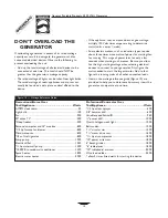
Page 10: ...ttage when selecting electrical devices to connect to your generator First figure the watts needed to start the largest motor Add to that figure the running watts of all other connected loads Items in the wattage reference guide Figure 10 are provided to help you to determine how many items the generator can operate at one time Recreational Home Uses Tool Appliance Watts AM FM clock radio 50 Light...

Page 11: ... the rotor and stator winding insulation Water and dirt buildup on the generator internal windings will eventually decrease the insulation resistance of these windings To Clean the Generator Use a damp cloth to wipe exterior surfaces clean Soft bristle brush may be used to loosen caked on dirt or oil A vacuum cleaner may be used to pick up loose dirt and debris Low pressure air not to exceed 25 ps...

Page 12: ...er in gasoline 8 Overchoking 9 Low oil level 10 Excessively rich fuel mixture 11 Intake valve stuck open or closed 12 Engine has lost compression 1 Set switch to Run 2 Clean or replace air cleaner 3 Fill fuel tank 4 Drain gas tank and fill with fresh fuel 5 Connect wire to spark plug 6 Replace spark plug 7 Drain gas tank fill with fresh fuel 8 Put choke lever to no choke position 9 Fill crankcase ...

Page 13: ...Generac Portable Products 3 500 Watt Generator 13 NOTES ...

Page 14: ...Generac Portable Products 3 500 Watt Generator 14 SCHEMATIC DIAGRAM ...

Page 15: ...Generac Portable Products 3 500 Watt Generator 15 WIRING DIAGRAM ...

Page 16: ...Generac Portable Products 3 500 Watt Generator 16 EXPLODED VIEW MAIN UNIT ...

Page 17: ... 33 65795 1 RECTIFIER Battery Charge 34 66849A 1 M5 0 8 x 20 Taptite 35 67022 1 GROMMET Rubber 36 84132 1 MODULE Drive 37 66386 1 ASSEMBLY Brush Holder Item Part Qty Description 38 66849 2 TAPTITE M5 0 8 x 16 39 B4871 1 COVER Bearing Carrier 41 86494 1 SCREW M6 1 0 x 16mm Wing 42 86292 1 SCREW 10 16 x 3 4 Self Drill 43 77395 4 NUT M6 Flange Lock 44 83465 4 GROMMET Tank 46 78831B 4 SCREW M6 1 0 x 6...

Page 18: ... 2 CIRCUIT BREAKER 18 Amp 9 82538 1 SWITCH On Off Rocker 10 84134 1 GROMMET Rubber 11 83514 1 CIRCUIT BREAKER 10 Amp 12 83970 1 CONTROL BOARD System Item Part Qty Description 13 84028 1 TRANSFORMER Idle Control 14 67022 1 GROMMET Rubber 15 85584 1 BAR Bus 16 84543A 2 SCREW 3 0 x 12mm 17 84543C 9 SCREW 3 5 x 18mm 18 84198 3 SHIELD Circuit Breaker 19 84197 1 BAR Circuit Breaker Retaining 21 75476 2 ...

Page 19: ...Generac Portable Products 3 500 Watt Generator 19 NOTES ...

Page 20: ...ch have been subjected to improper or unauthorized installation or alteration misuse negligence accident overloading overspeeding improper maintenance repair or storage so as in the COMPANY s judgement to adversely affect its performance and reliability NORMAL WEAR As with all mechanical devices the generator need periodic parts service and replacement to perform well This warranty will not cover ...

Reviews: