background image

26

Owner’s Manual for Flameless Heat Cart
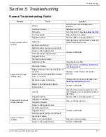
Troubleshooting

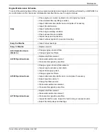
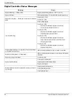
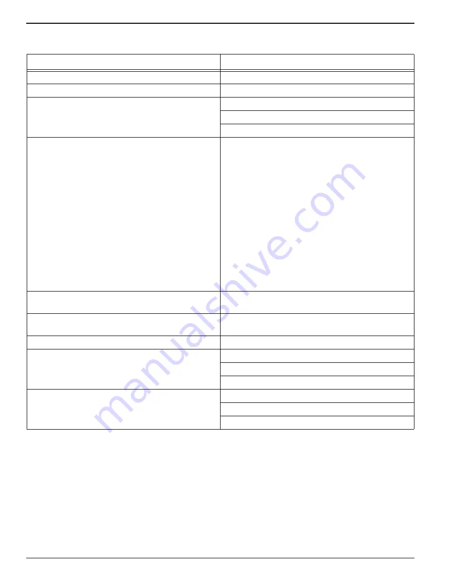
Digital Controller Status Messages

Message

Cause

Engine Warming — Please Wait

Engine coolant temperature < 140 °F (38 °C).

Engine Preheat

Wait approximately 10 seconds after heater powers up.

Engine is not ready — Check rpm, Fuel Level or Wait to 
Start

Engine rpm < 500

Fuel level < 10%

Wait to Start signal

Low Fuel Warning

Fuel level < 20%

Fuel level notification appears on screen

Low Fuel Level beacon turns on

Fuel level 

 16%

Fuel level notification appears on screen

Heat/fan load reduced to 50%

Fuel level 

 12%

Fuel level notification appears on screen

Open heat circuit and close scroll fan circuit

Drop engine to idle

Fuel level 

 8%

Fuel level notification appears on screen

Engine shuts down

Check heater settings or connections, then press Reset 
on the Machine Overview

IFM controller detected a short or break in a sender.

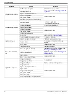
Heater is cooling down — Please wait

IFM controller detects heater is in cool down. ON button 
disabled.

Engine is going to shutdown

Fuel level 

 8%

Engine fault shutdown

Low engine oil pressure

High engine coolant temperature

Engine overspeed

Heater shutdown due to temperature; pressure or level 
out of range

High hydraulic temperature

Low hydraulic pressure

Low hydraulic level

Summary of Contents for MAC400HC

Page 1: ...E THIS MANUAL FOR FUTURE REFERENCE MAC400FHC Flameless Heat Cart Owner s Manual MODEL NUMBER _________________________ SERIAL NUMBER _________________________ DATE PURCHASED ________________________ 004390 ...

Page 2: ...ii Owner s Manual for Flameless Heat Cart 000393a WARNING CANCER AND REPRODUCTIVE HARM www P65Warnings ca gov ...

Page 3: ... Checklist 11 Engine Oil Level Check 11 Hydraulic Oil Check 11 Engine Coolant Check 11 Ducting Guidelines 12 Engine and Heater Startup 12 Adjusting Heater Output 13 AUTO Mode 13 MANUAL Mode 13 Heater and Engine Shutdown 14 Positive Air Shutdown PAS 14 Testing the PAS 15 Resetting the PAS 15 Section 4 Maintenance Maintenance 17 Maintenance Tasks 17 Daily Walk Around Inspection 17 Draining and Refil...

Page 4: ...iv Owner s Manual for Flameless Heat Cart This page intentionally left blank ...

Page 5: ...fixed to the unit are not all inclusive If using a procedure work method or operating technique that the manufacturer does not spe cifically recommend verify that it is safe for others and does not render the equipment unsafe Throughout this publication and on tags and decals affixed to the unit DANGER WARNING CAUTION and NOTE blocks are used to alert personnel to special instructions about a part...

Page 6: ...quipment or property damage Do not block air intake or restrict proper air flow Doing so could result in unsafe operation or damage to unit CAUTION 000240a Unit damage Do not stop engine before heating unit is cooled Doing so could result in unit damage CAUTION 000246 Equipment Damage The emergency stop switch is not to be used to power down the unit under normal operating circumstances Doing so w...

Page 7: ...lure to do so could result in death serious injury or property or equipment damage 000364 WARNING Control loss Trailer must be securely coupled to the hitch An incorrectly coupled trailer could result in loss of control death or serious injury 000360 Personal injury Do not operate unit during transport Doing so could result in death serious injury or property damage 000231a WARNING 000137a WARNING...

Page 8: ...4 Owner s Manual for Flameless Heat Cart Introduction and Safety This page intentionally left blank ...

Page 9: ...05 mm Electrical 12V Engine Fuel Diesel Number 1 D Number 2 D Engine Fuel Capacity 55 gal 208 L Engine Oil Capacity 11 qt 10 4 L Engine Coolant Capacity 2 5 gal 9 5 L HTF Capacity 24 gal 90 8 L Engine Fuel Rate at 100 prime 3 2 gph 12 1 Lph Run Time 18 8 hr Temperature Rise 180 F 82 C Pump Hydraulic piston pump Fan 18 25 in 46 36 cm diameter backward inclined Hitch Type Pintle ring Tire Size 4 in ...

Page 10: ...ilter L Engine oil dipstick C Hydraulic fluid breather separator M Diesel injection system D Hydraulic fluid fill N Fuel pump E Reservoir fluid level indicator P Fuel filters F Hydraulic fluid reservoir Q Engine oil filter G Hydraulic fluid filters R Engine oil cooler H Battery disconnect switch J Fluid drain oil fuel coolant 001918 001920 A B C D E F G H J K L M N P Q R ...

Page 11: ...Components A Muffler I Ducting storage rear B Air intake cap J Diesel fuel fill C Tie down rings K Street side engine access D Tow hitch L Temperature beacon amber E Parking brake lever M Low fuel level beacon blue F Curb side engine access G Control panel H Fork lift pockets 004395 A C B D E F G H C L M I J K ...

Page 12: ...0 antifreeze water mix which provides protection to approximately 58 F 50 C Coolant must be nitrite free and meet the perfor mance standards of ASTM D6210 NOTE Recommended coolant is ZEREX Nitrate Free Extended Life Antifreeze Coolant Test coolant yearly or every 1000 hours whichever comes first See the diesel engine manual for more infor mation Fuel System The engine is designed to use either Num...

Page 13: ...ocked position The locking lever A holds the tow bar in place Do not operate the unit without the parking brake engaged Lift the locking lever up and slowly lower the tow bar to disengage the parking brake NOTE Do not attempt to move the unit with the parking brake engaged equipment damage may occur Applicable Standard Recommendation JIS Japanese Industrial Standard No 2 DIN Deutsche Industrie Nor...

Page 14: ...tatus The controller will automatically stop the unit and display fault information if conditions occur outside of predetermined manufacturing parameters The controller can also display a variety of critical alerts diagnostics and recommendations The controller provides a variety of real time current operating condition data See the engine harness wiring diagrams for more information Button Positi...

Page 15: ...ase and wipe it clean with a clean lint free cloth 2 Insert oil dipstick fully into oil dipstick tube and then remove slowly 3 Oil level must be between the FULL and ADD marks on the oil dipstick 4 Add oil if necessary to adjust the level After add ing or changing the oil run the engine for one min ute before checking the oil level Wait 10 minutes to allow the engine to cool and oil to fully drain...

Page 16: ...een displays Start Engine WARNING Burn hazard Do not remove ducting until all air pressure has been emptied from hose duct Failure to do so could result in severe injury 000288 000108 WARNING Hot Surfaces When operating machine do not touch hot surfaces Keep machine away from combustibles during use Hot surfaces could result in severe burns or fire WARNING Crushing hazard Verify parking brake is p...

Page 17: ... blowing from ducts the amber strobe light on top of the unit activates and the screen displays Heater On Press OFF to stop the heater Figure 3 5 Heater On Adjusting Heater Output Use the up and down arrows to adjust temperature selec tion to desired outlet temperature The options are 100 F 38 C 120 F 49 C 140 F 60 C and 160 F 71 C Monitor regularly and adjust as needed AUTO Mode In AUTO mode outp...

Page 18: ...itive Air Shutdown PAS See Figure 3 10 This unit is equipped with a manually activated positive air shutdown PAS on the air intake If the atmosphere contains combustible propane or natural gas a positive air shutdown can be activated to prevent these gases from being drawn into the engine and ignit ing The PAS system stops the engine by closing an internal valve and obstructing intake air See Figu...

Page 19: ...ve is closed by verifying that the reset knob is rotated completely clockwise If any resistance is felt or the valve does not close contact Generac Mobile Products Technical Support Resetting the PAS The emergency PAS system must be reset after each emergency event according to the steps below 1 Turn the control power switch to OFF O 2 Locate the PAS valve located inside the cabinet of the unit 3 ...

Page 20: ...16 Owner s Manual for Flameless Heat Cart Operation This page intentionally left blank ...

Page 21: ...he vents and on top of unit Inspect outer cover for significant damage beyond scuffs and small nicks Inspect for wire abrasion Inspect the fan belt for cracking fraying and stretching Verify the belt is properly seated in the pulley grooves Check coolant Check electrical connectors battery and ground points Look for loose or missing hardware Check all flexible rubber hoses for deterioration Check ...

Page 22: ...ollowing is the manufacturer s recommended maintenance sched ule The maintenance items need to be performed more frequently if the unit is used in severe applications such as very high or very low ambient conditions or extremely dirty or dusty environments Use the unit hour meter or calendar time whichever occurs first from the previous maintenance interval to determine the next required maintenan...

Page 23: ...cking Every Six Months Inspect wheel bearings Every 12 Months Replace coolant At 50 Operation Hours Break In Change engine oil and oil filter Change engine fuel filters At 250 Operation Hours Replace fuel filter element Clean water sedimenter element Clean electromagnetic pump filter At 500 Operation Hours Change engine oil and oil filter element Inspect engine accessory drive belts Inspect fuel s...

Page 24: ...pply system Clean positive crankcase ventilation valve Inspect injection nozzle Change fuel filter element Clean water sedimenter element Clean electromagnetic pump filter After 1500 Operation Hours All hours based checks and maintenance should now be performed every 250 hours When servicing these items consult the equipment supplier NOTE All service and maintenance or repairs are recommended to b...

Page 25: ...equired the battery must be replaced with one of equivalent size voltage and CCA cold crank amp capacity Minimum CCA for this unit is 950 Contact a GMP ASD for correct battery size A new battery must be filled with the proper electrolyte and be fully charge before installing Battery cables are connect to the unit at the factory Connect cables to battery posts as follows NOTE Turn the battery disco...

Page 26: ...ra tion Store in a safe location do not position near or on top of any combustible materials observe any local state or national codes or regulations Store in a low moisture low dust area Disconnect the negative cable from the battery Return to Service Follow the guidelines below for engines and units that have not been operated for three to six months Conduct a thorough inspection of the unit bef...

Page 27: ...tric start Discharged battery Replace battery See Battery Installation and Replacement Battery terminal is disconnected loose or corroded Replace corroded part s and tighten securely Starter ground terminal is disconnected loose or corroded Excessive engine oil viscosity Change with oil of correct viscosity See Draining and Refilling the Oil Starter or electrical system failure Contact a GMP ASD E...

Page 28: ... is clogged with dust Clean with soft brush Subtank cap is not tightened Tighten or replace sub tank cap Fouled coolant Clean inside of radiator and change coolant Oil in coolant Contact a GMP ASD Thermostat failure Change thermostat Oil pressure does not rise Incorrect engine oil viscosity Change with oil of correct viscosity See Draining and Refilling the Oil Insufficient engine oil Replenish en...

Page 29: ...on Blower fan operating incorrectly Remove ducting check blower fan opera tion No low heat condition Incorrect heater setting target tempera ture too low Adjust heater output See Adjusting Heater Output Access doors are open Close all access doors Insufficient HTF hydraulic oil level Check level on tank sight glass adjust as needed Inspect HTF hoses for leaks or loose fittings Check fluid for foam...

Page 30: ... load reduced to 50 Fuel level 12 Fuel level notification appears on screen Open heat circuit and close scroll fan circuit Drop engine to idle Fuel level 8 Fuel level notification appears on screen Engine shuts down Check heater settings or connections then press Reset on the Machine Overview IFM controller detected a short or break in a sender Heater is cooling down Please wait IFM controller det...

Page 31: ...Owner s Manual for Flameless Heat Cart 27 Installation Diagrams Section 6 Installation Diagrams Engine Harness 1 of 3 ...

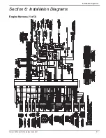
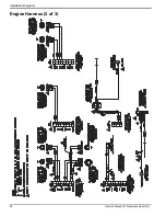
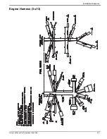
Page 32: ...28 Owner s Manual for Flameless Heat Cart Installation Diagrams Engine Harness 2 of 3 ...

Page 33: ...Owner s Manual for Flameless Heat Cart 29 Installation Diagrams Engine Harness 3 of 3 ...

Page 34: ...t Cart Installation Diagrams Hydraulic System Schematic M 1 H1 H1 H1 H1 H1 H1 M 1 P1 H1 V1 V1 Large Hydraulic Exchanger Small Hydraulic Exchanger Hydraulic Oil Tank Fan Pressure Regulating 3 Way Valve Start up Bypass 3 Way Valve Filters ...

Page 35: ...Owner s Manual for Flameless Heat Cart 31 Installation Diagrams Hydraulic Heat System ENGINE RADIATOR C60 HYD EXCHANGER LARGE EXHAUST EXCHANGER ...

Page 36: ...32 Owner s Manual for Flameless Heat Cart Installation Diagrams This page intentionally left blank ...

Page 37: ...Owner s Manual for Flameless Heat Cart 33 Installation Diagrams This page intentionally left blank ...

Page 38: ...34 Owner s Manual for Flameless Heat Cart Installation Diagrams This page intentionally left blank ...

Page 39: ......

Page 40: ...ights reserved Specifications are subject to change without notice No reproduction allowed in any form without prior written consent from Generac Mobile Products LLC Generac Mobile Products LLC 215 Power Drive Berlin WI 54923 GeneracMobileProducts com 800 926 9768 920 361 4442 ...

Reviews: