background image

Wiring Diagrams

44

Owner’s Manual for MLT6SC Light Tower

AC Wiring Diagram

90500_E_03.09.18

Summary of Contents for Magnum MLT6SC

Page 1: ...Owner s Manual Light Tower MLT6SC SAVE THIS MANUAL FOR FUTURE REFERENCE For technical assistance contact www generacmobileproducts com Technical Support 1 800 926 9768 ...

Page 2: ...have the equipment checked periodically by a GMP ASD Normal maintenance service and replacement of parts are the respon sibility of the owner operator and as such are not considered defects in materials or workmanship within the terms of the war ranty Individual operating habits and usage may contribute to the need for additional maintenance or service Unit Model Number Unit Serial Number Engine M...

Page 3: ... Operation Light Tower Setup 25 Prestart Checklist 26 Raising the Mast Manual Winch 26 Raising the Mast Electric Winch If Equipped 27 Starting the Unit 28 Preparing for Start Up with PowerZone Controller If Equipped 29 Select AUTO or MANUAL Mode 29 Manually Starting the Unit 29 Light Operation 29 Light Operation with PowerZone Controller If Equipped 30 Engine Derating 30 Wet Stacking 30 Dusk to Da...

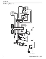
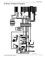
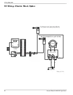
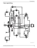
Page 4: ...ce 39 Section 5 Troubleshooting General Troubleshooting 41 Troubleshooting the Lights 42 Section 6 Wiring Diagrams Mast Junction Box Wiring and Light Connections 43 AC Wiring Diagram 44 AC Wiring PowerZone If Equipped 45 DC Wiring Diagram 46 DC Wiring PowerZone If Equipped 47 DC Wiring Electric Winch Option 48 Trailer Lights Wiring 49 Section 7 Service Log ...

Page 5: ... all inclusive If using a procedure work method or oper ating technique that the manufacturer does not specifically recommend verify that it is safe for others and does not render the equipment unsafe Throughout this publication and on tags and decals affixed to the unit DANGER WARNING CAUTION and NOTE blocks are used to alert personnel to special instructions about a particular operation that may...

Page 6: ...Failure to do so could result in death or serious injury 000105 DANGER Explosion and Fire Fuel and vapors are extremely flammable and explosive Add fuel in a well ventilated area Keep fire and spark away Failure to do so will result in death or serious injury 000147 WARNING Risk of Fire Unit must be positioned in a manner that prevents combustible material accumulation underneath Failure to do so ...

Page 7: ...188 DANGER Electrocution Do not wear jewelry while working on this equipment Doing so will result in death or serious injury DANGER Electrocution DO NOT use the unit if electrical cord is cut or worn through Doing so will result in death or serious injury 000263a 000188 DANGER Electrocution Do not wear jewelry while working on this equipment Doing so will result in death or serious injury 000137a ...

Page 8: ...ng Ambient air temperature is above 120 F 49 C Operating Safety Positioning the Unit The area immediately surrounding the unit should be dry clean and free of debris Position and operate the unit on a firm level surface If the unit is equipped with a frame grounding stud follow the National Electrical Code NEC state and local regulations when connecting Starting the Unit 000192 DANGER Explosion an...

Page 9: ... important operating instructions and warn of dangers and hazards Wear heavy leather gloves when handling winch cables Never let cables slip through bare hands Only use mild soap and water to clean the lens covers Other chemicals may damage the lens covers WARNING Electrocution Do not set up or operate this unit if severe weather is expected Lightning strikes can kill or cause severe injury even i...

Page 10: ...Inspect trailer tires for wear and proper inflation Verify wheel lug nuts are present and tightened to the specified torque Safe Towing Techniques Practice turning stopping and backing up in an area away from heavy traffic prior to transporting the unit Maximum recommended speed for highway towing is 45 mph 72 km h Recommended off road towing speed is 10 mph 16 km h or less depending on terrain Wh...

Page 11: ...bel not shown 2 Setup and Take Down Instructions Manual 16 Neutral Bonded to Frame 3 Danger Overhead Power Lines 17 Not A Step 4 Warning Electrical Storms and High Wind 18 Warning High Temperature Do Not Remove Guard 5 Owner s Manual Location 19 Mast Junction Box Wiring inside 6 Electric Shock Hazard 20 Warning Do Not Retract Outriggers With Tower Up 7 Warning Pressurized Liquid 21 Stowed Position...

Page 12: ...N INSTALLATION TAKE DOWN ABBAU DESINSTALACIÓN DÉMONTAGE 4 X2 3 B A C I O I O I O I O 15 MIN STOP X2 2 1 Inch 25 mm x3 3 B 4 A C 0 5 1 I O I O I O I O STOP 6 5 1 2 0 5 1 SET UP AUFSTELLUNG INSTALACIÓN INSTALLATION X2 2 C B 4 5 6 TAKE DOWN ABBAU DESINSTALACIÓN DÉMONTAGE 15 MIN STOP 1 3 4 X2 1 Inch 25 mm x3 3 2 B A A C 006447 1 2 ...

Page 13: ...ller dans des vents excédant 60 mph ou pendant les orages electriques DO NOT set up unit in winds exceeding 60 mph or during electrical storms ELECTRICAL STORMS HIGH WIND 60 mph WARNING Der kontakt mit elektrischen Hochspannungsleitungen kann zu schweren oder lebensgefährlichen Verletzungen führen Den Beleuchtungswagen nie direkt unter Hochspannungsleitungen aufstellen El contacto con las líneas e...

Page 14: ... to tow vehicle 4 Attach safety chains using a cross pattern WWDFK EUHDNGRZQ FKDLQ WR YHKLFOH KHFN WUDLOHU OLJKWV TOWING INSTRUCTIONS INSTRUCCIONES PARA REMOLQUE 1 Lea el manual del operador 2 Use un enganche adecuado para la capacidad de peso bruto del vehículo del remolque 3 Enganche firmemente el remolque al vehículo de remolque 4 Enganche las cadenas de seguridad en forma cruzada QJDQFKH DO YH...

Page 15: ...arathon Model 201CSA5423 Output Standby kW kVA 6 0 6 0 Output Voltage volts 120 240 1 phase Output Amperes 120V 240V amperes 50 25 Frequency Hz Hertz 60 Weights Dry Weight lbs kg 1316 597 Operating Weight lbs kg 1586 719 Capacities Fuel Tank Volume gal L 40 75 154 26 Usable Fuel Volume gal L 39 9 151 04 Coolant including engine qt L 5 0 4 7 Oil including filter qt L 4 6 4 4 Maximum Run Time at Ful...

Page 16: ...FC626B Manufactured by Generac Mobile Products LLC 920 361 4442 800 926 9768 TIRE AND LOADING INFORMATION RENSEIGNEMENTS SUR LES PNEUS ET LE CHARGEMENT SEE OWNER S MANUAL FOR ADDITIONAL INFORMATION VOIR LE MANUEL DE L USAGER POUR PLUS DE RENSEIGNEMENTS MANUFACTURED BY FABRIQUE PAR Generac Mobile Products LLC DATE 00 0000 GVWR PNBV 000KG 0000LBS COLD INF PRESS PRESS DE V I N N I V 00000000000000000...

Page 17: ...move jack from tongue weldment Hold jack vertically and extend until weldment on jack is aligned with tongue weldment 4 See Figure 2 3 Install jack and secure with clevis D Figure 2 3 Jack Installed 5 See Figure 2 2 Remove pins B and C 6 See Figure 2 4 Using both hands slowly lower trailer tongue into tow position NOTE Varying levels of effort may be required depending on terrain Figure 2 4 Lower ...

Page 18: ...levels of effort may be required depending on terrain Figure 2 7 Pivot Trailer Tongue Into Storage Position 5 See Figure 2 8 Install pins B and C at locations shown to secure trailer tongue in storage position Figure 2 8 Install Pins and Rotate Jack 6 Remove clevis and remove jack A from tongue weldment 7 Completely retract jack 8 Rotate jack 90 counterclockwise place jack on tongue weldment and i...

Page 19: ...r s Manual for MLT6SC Light Tower 15 Unit Dimensions Figure 2 9 Unit Dimensions Specifications are subject to change without notice A B C D E MLT6SC 118 in 3 m 101 in 2 6 m 23 ft 7 m 57 in 1 5 m 120 5 in 3 1 m 006451 A E D C B ...

Page 20: ...tions Figure 2 10 Component Locations Front and Left Side A Grounding studs Interior On enclosure floor behind controller Exterior On bumper E Tongue jack B Outriggers and jacks 2 F Mast rotation knob C Fuel fill G Winch D Tie down location H Lights 4 008096 A B A C H G F E D ...

Page 21: ...igure 2 11 Component Locations Rear and Right Side J Central lift point M Tandem tow mount optional not shown K Engine radiator access hood N Hood latch L Forklift pocket P Key start controller or PowerZone DLA controller optional not shown 006453 L K L P M J D N ...

Page 22: ...set button F 240VAC 30A twist lock receptacle Customer convenience receptacle for use in connecting auxiliary equipment such as fans pumps drills G Engine hour meter Displays number of hours the engine has run H Main circuit breaker 240V 30A breaker which disconnects power from the lights and control panel I Control power switch Turns the controller ON and OFF J PowerZone controller Monitors the u...

Page 23: ...stal Display LCD Window Displays the various operating screens By viewing these screens the operator can monitor both the engine and generator status while the unit is running B Select LED Illuminates when the unit is running in AUTO mode C Start LED Illuminates when the unit is running in MANUAL mode D Start Button Starts the engine if there are no shutdown errors and the engine is in ready to st...

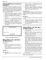
Page 24: ...ered up and the unit management software is loaded It displays the controller mode total operating hours hours left until the next service interval engine operating status and engine rpm If the unit is in AUTO mode the Home screen may also display whether the scheduler or dusk to dawn are enabled Figure 2 15 Home Screen Battery Voltage Screen See Figure 2 16 Displays the engine battery voltage A n...

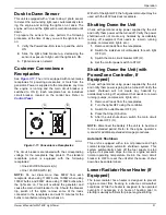
Page 25: ...le in operation Figure 2 19 Generator Screen Dusk to Dawn Screen NOTE This feature will only work in AUTO mode See Figure 2 20 The Dusk to Dawn screen enables or disables the dusk to dawn function This function uses a photo sensor to detect the surrounding light level auto matically starting the engine and turning the lights on at dusk The engine will run and the lights will remain illumi nated un...

Page 26: ... Screen See Figure 2 24 The Alarms screen displays all the alarms warnings and engine Diagnostic Trouble Code DTC faults When an alarm occurs the controller automatically switches to this screen and remains there until the alarm is cleared The Stop LED also flashes Figure 2 24 Alarms Screen Warnings are non critical alarm conditions and do not affect the operation of the generator system They serv...

Page 27: ...r oil filter and air filter Figure 2 25 Maintenance Screen Event Log Screen See Figure 2 26 The controller s event log displays a list of the last 15 recorded electrical trips or shutdown events and the engine hours at which they occurred Once the log is full any subsequent electrical trip or shutdown alarm overwrites the oldest entry in the log The log always contains the most recent shutdown ala...

Page 28: ...Light Tower About Screen See Figure 2 27 The About screen contains information about the controller such as the controller s date and time the product and USB identification number and the application and engine version Figure 2 27 About Screen 003783 ...

Page 29: ...grounding stud B is located on the rear frame of the trailer near the left side outrigger For ground ing requirements follow local state and National Electrical Code NEC regulations 5 See Details C D Pull the locking pins C on the outriggers D and pull each outrigger out until the spring loaded locking pin snaps back into place Pull the locking pin on each outrigger jack F and rotate each jack 180...

Page 30: ...he battery disconnect switch on if equipped Inspect the engine fan belt tension and condition Inspect the engine fan belt guard Inspect the engine exhaust system for loose or rusted components Verify all covers are in place and secure Raising the Mast Manual Winch 1 Set up and level the unit See Light Tower Setup 2 See Figure 3 2 Inspect the mast cables for excessive wear or damage Verify the cabl...

Page 31: ...es for excessive wear or damage Verify the cables are properly centered in each pulley A Inspect the electrical cord for damage DETAIL D STOP 002532 C D B A DANGER Electrocution DO NOT use the unit if electrical cord is cut or worn through Doing so will result in death or serious injury 000263a WARNING 000266 Tipping hazard Extend the outriggers and level the unit before raising the mast Keep the ...

Page 32: ...sconnect power to the upper electric winch to prevent overextending the mast Starting the Unit NOTE If the engine was run out of fuel or the fuel tank was drained it may be necessary to purge the fuel lines Refer to the engine operator s manual supplied with the unit 1 See Figure 3 4 Verify the main circuit breaker and individual circuit breakers for each of the lights are OFF O Figure 3 4 Circuit...

Page 33: ...on the LCD screen and the Stop LED illuminates to indicate that the controller is in STOP mode Press the Start button to initiate the startup procedure If there are no existing engine faults the engine will start and the Start LED will illuminate NOTE The engine can be started from any screen It may take a few seconds for the engine to run smoothly and reach its governed operating speed 5 If the e...

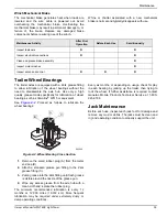
Page 34: ...ature and running smoothly switch the main circuit breaker ON I 2 To turn the light s ON press the Select button To turn the light s OFF press the Select button Engine Derating All units are subject to derating for altitude and tempera ture Derating reduces the available power for operating tools and accessories connected to the outlets For every increase in 1 000 ft 305 m of elevation engine perf...

Page 35: ...tput may be used with the 240V twist lock receptacle Shutting Down the Unit Check with personnel using power supplied by the unit and notify them power will be turned off Verify the power shutdown will not create any hazards by accidentally turning off equipment that needs to remain running pumps compressors lights etc 1 Remove all loads from the receptacles 2 Switch the individual circuit breaker...

Page 36: ... mph 72 km h b Graded gravel 25 mph 40 km h c Cross country 15 mph 24 km h Telemetry If Equipped The digital telemetry option enables the operator to remotely monitor the unit fuel level A transmitter inside the engine compartment sends real time equipment sta tus information to the user via cellular or satellite connec tion Spark Arrester If Equipped A spark arrester installed on the exhaust may ...

Page 37: ...over A Figure 3 14 Manually Lowering the Mast 2 Attach drill chuck firmly to exposed motor shaft B 3 Using drill slowly rotate motor shaft counterclock wise to lower mast 4 Detach drill chuck and install motor cover after mast is completely lowered Towing the Unit Once engine is shut down and mast and lights are properly stowed proceed as follows to prepare unit for towing 1 Raise outrigger jacks ...

Page 38: ...t capacity For approxi mate weights refer to Specifications 2 Close and lock all hoods and doors 3 See Figure 3 16 Stow mast and lights in travel position as shown Figure 3 16 Lifting Points IMPORTANT NOTE Always remain aware of people and objects around the unit while preparing maneu vering and lifting the unit NOTE When lifting the unit attach any slings chains or hooks directly to the central l...

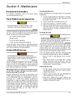
Page 39: ... PowerZone controller verify main circuit breaker is OFF Otherwise verify key switch is set to OFF 2 Verify circuit breakers are switched OFF O 3 Disconnect negative terminal on battery 4 Attach a Do Not Start sign to control panel This will notify others the unit is being serviced and reduce the chance of others inadvertently trying to operate the unit Cleaning the Unit Always clean unit after ea...

Page 40: ... ADD mark on the oil dipstick Normal operating level is within the cross hatch pattern between the FULL and ADD markings on the oil dipstick Only add oil if oil level is below the ADD mark on the bottom of the cross hatch pattern on the oil dipstick DO NOT OVERFILL the crankcase Check fuel level If unit is connected to a remote start or transfer switch verify the remote switch is also off and tagg...

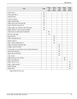
Page 41: ...s for debris clean as required Inspect light tower winch for proper operation Check fuel and coolant clamps for tightness Drain water separator Sample coolant Inspect and adjust fan belt Sample engine oil Clean replace air filter element Replace fuel system secondary filter Change engine oil and filter Check engine sensors oil pressure and coolant temperature Lubricate leveling jacks Inspect hoses...

Page 42: ...fied direction to lift The ratchet MUST make a loud clicking sound while winding the cable Lowering the Lights Referring to the Lift Let Down decal on the winch turn handle according to the specified direction to lower No clicking will be heard because the brake system is activated Maintenance The following procedures should be performed at least annually 1 The gears and bushings of the winch must...

Page 43: ... plug A from the metal end cap B 2 Attach a standard grease gun fitting to the Zerk grease fitting C 3 Pump grease into the Zerk fitting until fresh grease is visible around the nozzle of the grease gun 4 Wipe any excess grease from the axle hub with a clean cloth and replace the rubber plug The minimum recommended lubrication is every 12 months or 12 000 miles 19 312 km More frequent lubrication ...

Page 44: ...Maintenance 40 Owner s Manual for MLT6SC Light Tower This page intentionally left blank ...

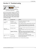
Page 45: ...eeded Oil leaking from engine Inspect the engine for leaks Oil pressure switch failure Refer to OEM engine operator s manual to identify corrective action High coolant temperature shutdown Low coolant level Add coolant if needed Allow engine to cool then check coolant level in radiator Restart engine and check coolant temperature Stop engine immediately if coolant temperature is 210 F 99 C or more...

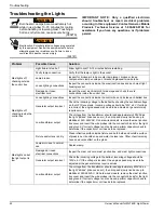
Page 46: ...Check the incoming voltage to the ballast by checking the available voltage on the GFCI receptacle Incoming voltage should be 120V 5V If voltage is incorrect the engine speed may need to be adjusted or generator may require service Low transformer output The voltage from the transformer should read approximately 400VAC as the light strikes induces an arc then drop and slowly rise back up to stabil...

Page 47: ...Wiring Diagrams Owner s Manual for MLT6SC Light Tower 43 Section 6 Wiring Diagrams Mast Junction Box Wiring and Light Connections 00768 1 3 2 4 ...

Page 48: ...Wiring Diagrams 44 Owner s Manual for MLT6SC Light Tower AC Wiring Diagram 90500_E_03 09 18 ...

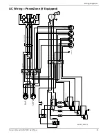
Page 49: ...Wiring Diagrams Owner s Manual for MLT6SC Light Tower 45 AC Wiring PowerZone If Equipped 90616_B_03 09 18 ...

Page 50: ...SPLICE SPLICE 12 11 10 9 9 10 11 12 A B C TO OPTIONAL ELEC MAST VOLTAGE CONTROLLER FROM CAT ALT WHT YL BLK WHT WHT BLK RD VIO RD 1 2 3 4 5 6 ENG GND WHT YL WHT BLK MITSU CONN VI YL ENG GND BLUNT BLUNT A B C D RUN STRT GLW BK WT RD WT MAIN CIRCUIT BREAKER LOAD LINE RELAY TIME DELAY N O N C COM HOUR METER COIL BK WT STARTER SWITCH SPLICE BK WT BK WT VI YL VI YL 10 AMP CIRCUIT BREAKER RD RD VI YL RD ...

Page 51: ...1387 1 2 1 20 1 2 1387 1 1 1 6 5 1 2 5 1 2 1387 287387 3 1 2 7 21 5 9 7 25 72 5 5 7 5 7 7 7 7 7 5 72 1 5 72 1 5 72 1 0 67 83 0 67 2 1 6 67 0 1 872 02 5 72 1 1 9 72 1 5 5 6 6725 72 5 72 5 72 5 6 5 0 7 6 5 0 5 72 1 7 1 9 5 72 1 7 1 1 1 9 7 1 7 237 21 75 1 2 6 83 6723 2 1 6723 7 03 5 785 2 35 6685 3 272 6 1625 5 72 1 7 63 5 5 7 2 0 1 75 237 21 5 0 2 5 7 7 67 57 5 2 35 6685 51 1 6 7 1 51 1 29 5 7 6 7 ...

Page 52: ... WINCH BK BK YL BL CONTACTOR 1 BATTERY GN BN BK BK RD BL YL 1 2 1 2 3 4 5 6 7 8 1 2 3 4 5 6 7 8 12 11 10 9 9 10 11 12 A B C BN UP DOWN SWITCH 1 BK VI BN BK VI BN BK VI TOP SWITCH DOWN STOP BOTTOM SWITCH UP STOP BK BK WT BN BL YL BK BK YL BK RD RELAY TIME DELAY N O N C COM 90596_A_07 19 16 ...

Page 53: ...WT WT WT WT BK WT VI YL WT AMBER L AMBER R MARKER MARKER VI YL BK WT TO FUEL CKT BN BN BN WT WT WT RING GND LICENSE PLATE PANEL LIGHT BK WT BK WT BK BK WT WT BK BN BN WT BK BN BN BN WT BK BN WT BN WT WT BN BN SPADE SPADE SPADE SPADE SPADE SPADE SPADE SPADE SPADE SPADE SPADE SPADE WT BN YL GN B C A D SPADE SPADE SPADE C B A D SPADE SPADE SPLICE SPLICE SPADE SPADE SPADE SPADE SPADE SPADE SPADE SPLIC...

Page 54: ...Wiring Diagrams 50 Owner s Manual for MLT6SC Light Tower This page intentionally left blank ...

Page 55: ..._________________________________________________________ ______________________________________________________________________________________________ ______________________________________________________________________________________________ ______________________________________________________________________________________________ _________________________________________________________...

Page 56: ...________________________________________________ ___________________________________________________________________________ ___________________________________________________________________________ ___________________________________________________________________________ ___________________________________________________________________________ _______________________________________________...

Page 57: ...Service Log Owner s Manual for MLT6SC Light Tower 53 This page intentionally left blank ...

Page 58: ...Service Log 54 Owner s Manual for MLT6SC Light Tower This page intentionally left blank ...

Page 59: ......

Page 60: ...ghts reserved Specifications are subject to change without notice No reproduction allowed in any form without prior written consent from Generac Mobile Products LLC Generac Mobile Products LLC 215 Power Drive Berlin WI 54923 GeneracMobileProducts com 800 926 9768 920 361 4442 ...

Reviews: