background image

SAVE THIS MANUAL FOR FUTURE REFERENCE

Register your Generac product at:

WWW.GENERAC.COM

1-888-GENERAC

(1-888-436-3722)

Installation Manual

Generac PWRcell™ Inverter

009954

(000209b)

WARNING

Loss of life. This product is not intended to 
be used in a critical life support application. 
Failure to adhere to this warning could result 
in death or serious injury.

Register your Generac product at:

https://register.generac.com/

1-888-GENERAC

(888-436-3722)

Para español, visita: 

http://www.generac.com/service-support/product-support-lookup

Pour le français, visiter: 

http://www.generac.com/service-support/product-support-lookup

Summary of Contents for PWRcell X11400 Series

Page 1: ...s product is not intended to be used in a critical life support application Failure to adhere to this warning could result in death or serious injury Register your Generac product at https register generac com 1 888 GENERAC 888 436 3722 Para español visita http www generac com service support product support lookup Pour le français visiter http www generac com service support product support looku...

Page 2: ... page See Serial Number Locations When contacting an Independent Authorized Service Dealer IASD or Generac Customer Service always supply the complete model number and serial number of the unit Table 1 Generac PWRcell Inverter Important Information Unit Model Number Unit Serial Number Date Purchased Commissioning Date 000393a WARNING CANCER AND REPRODUCTIVE HARM www P65Warnings ca gov ...

Page 3: ...Section 4 Installing PWRcell Inverter Mounting the Inverter 11 Section 5 Electrical Connections Generac PWRcell Inverter Wiring Compartment 13 Accessing Wiring Compartment 13 Knockout Dimensions and Locations 14 Wiring Guidelines 15 Grounding Bar Wiring 15 DC Wiring 16 AC Wiring 16 Protected Load 17 Current Transformers CTs 18 Other Accessories 20 Section 6 Commissioning and Setup System Configura...

Page 4: ...iv Installation Manual for Generac PWRcell Inverter This page intentionally left blank ...

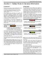
Page 5: ...s manual to any individual that will use this unit and instruct them on how to correctly start operate and stop the unit in case of emergency Safety Rules The manufacturer cannot anticipate every possible cir cumstance that might involve a hazard The alerts in this manual and on tags and decals affixed to the unit are not all inclusive If using a procedure work method or operating technique that t...

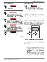
Page 6: ...ments could result in death serious injury and equipment or property damage 000182a WARNING Equipment damage Only qualified service personnel may install operate and maintain this equipment Failure to follow proper installation requirements could result in death serious injury and equipment or property damage 000640 WARNING Equipment damage Connecting inverter to electric utility grid must only be...

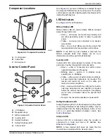
Page 7: ...ce Failure to do so will result in death serious injury equipment and property damage NOTE A loss of grid power will not de energize REbus in a system configured to island or provide backup power See Figure 1 1 Shutdown button A on the Generac PWRcell Inverter control panel activates Safety Shutdown Safety Shutdown signals connected devices to shutdown and limit output voltage to a safe level An e...

Page 8: ...Safety Rules General Information 4 Installation Manual for Generac PWRCell Inverter This page intentionally left blank ...

Page 9: ... current nanogrid A 30 Maximum input source backfeed current to input source nanogrid A 30 Output power factor rating AC 1 Operating Voltage range AC 2ph V rms 108 130 Operating Voltage range AC 3ph V rms 106 132 Operating frequency range or single frequency Hz 59 6 60 4 Nominal output voltage AC V rms 120 240 208V 3ph Normal output frequency AC Hz 60 Maximum continuous output current AC A rms 32 ...

Page 10: ...erac PWRcell Inverters disconnect from the grid and provide AC power to support protected loads when configured to do so All Generac PWRcell products use the REbus 380 VDC nanogrid to connect energy sources storage and loads The REbus nanogrid automates the flow of power to enable plug and play setup and operation of Generac PWRcell equipment For more information about REbus visit www generac com ...

Page 11: ...nogrid itself See display A for more information about the specific fault detected Inverter LED Inverter LED D communicates the status of the utility grid and or inverter through LED color and state Green utility is connected and within normal operational voltage and frequency Blinking green system is in standby mode powering up or initializing Yellow utility grid is not within normal conditions b...

Page 12: ...8 Installation Manual for Generac PWRcell Inverter General Information This page intentionally left blank ...

Page 13: ...ns included in this manual and use appropriate practices for all product wiring and installa tion Note on DC Wiring and the NEC Some electricians or installers may be unfamiliar with DC wiring in a residential setting Note the following NEC 690 31 G for DC PV circuits in buildings NEC 215 12 C 2 for correct DC wiring coloring NEC 210 5 C 2 for identification of DC conduc tors carrying more than 50...

Page 14: ...s All over voltage and under voltage trip conditions result in a 300 second restart delay time after the trip threshold has been exceeded for the listed number of cycles Frequency Trip Thresholds See Table 3 2 for the default fixed frequency trip set points All over frequency and under frequency trip condi tions result in a 300 second restart delay time after the trip threshold has been exceeded f...

Page 15: ...r to enter intake or exhaust vents See Figure 4 1 Observe all mounting clearances 009989 A F B G H I C D E K L J Figure 4 1 Mounting Clearances A 4 in 101 6 mm G 24 5 in 622 3 mm B 19 25 in 489 mm H 8 in 203 2 mm C 8 in 203 2 mm I 28 5 in 723 9 mm D 20 in 508 mm J 28 in 711 2 mm E 8 5 in 215 9 mm K 36 in 914 4 F 8 in 203 2 mm L Floor 2 Verify fasteners are suitable for the mounting surface and can...

Page 16: ...Installing PWRcell Inverter 12 Installation Manual for Generac PWRcell Inverter This page intentionally left blank ...

Page 17: ...ety shutdown and turn PWRcell Disconnect Switch OFF on all connected batteries before performing service Failure to do so will result in death serious injury equipment and property damage 000642 DANGER Electrocution Verify all system voltages are safe before wiring Disconnect all AC and DC sources of power before touching terminals Failure to ensure no dangerous voltages are present on conductors ...

Page 18: ...ing washers to accommodate smaller conduit sizes Install rain tight or wet locations hubs in compliance with UL514B Table 5 3 Combination Knockout Size and Quantity Combination Knockout Size Quantity 3 4 X 1 6 1 2 X 3 4 7 5 517 140 13 5 910 150 13 2 638 67 1 654 42 1 969 50 2 819 71 60 2 212 56 18 1 374 34 91 2 165 55 2 165 55 1 083 27 50 2 165 55 1 929 49 1 875 47 63 1 811 45 99 119 3 01 1 648 41...

Page 19: ... 310 15 B 16 formerly Table 310 16 Torque all terminals as specified in Table 5 4 Table 5 4 Terminal Toques Wiring Terminal Torque AC terminals 13 3 to 15 9 in lb 1 5 to 1 8 Nm DC terminals 12 in lb 1 35 Nm Ground terminals 4 to 6 AWG 45 in lb 5 Nm 8 AWG 40 in lb 4 5 Nm 10 to 14 AWG 35 in lb 4 Nm STOP terminals 1 9 to 2 2 in lb 0 22 to 0 25 Nm Grounding 000643 WARNING Equipment damage Never connec...

Page 20: ...two pole circuit breaker Breakers indicate state and may be used to disconnect DC circuits Breakers disconnect both ungrounded DC conductors simultaneously Torque all terminals as specified in Table 5 6 Table 5 6 DC Wiring Terminal Specifications Wire Size Terminal Temp Range Wire Min Temp Rating Torque 18 6 AWG 75 10 mm 40 to 266ºF 40 to 130ºC 194ºF 90ºC 12 in lb 1 35 Nm AC Wiring NOTE The instal...

Page 21: ... only using PV array and battery power This transition takes place in a fraction of a second NOTE To create a protected loads panel connect the circuits that require backup to a subpanel Connect this subpanel to the protected loads terminals The protected loads continuous output is 8 kW or 33 3 amps at 240V The inverter can surge up to 50 A for motor starting capabilities A PV Array B Generac PWRc...

Page 22: ...gs For manual IP setup see the Generac PWRcell Inverter Owner s Manual NOTE It is the installer s responsibility to verify the Internet connection is reliable and secure Generac recommends using a hardwired connection to provide Internet connectivity Generac does not support using any wireless or power line carrier network devices Use these devices at your own discretion Current Transformers CTs C...

Page 23: ...Orange CT3 2 Green Orange CT3 3 White Orange White Green CT2 4 Blue Blue CT1 5 White Blue White Blue CT1 6 Orange Green CT2 7 White Brown White Brown Not Used 8 Brown Brown Not Used CT Calibration Install CTs before powering ON the inverter The inverter automatically detects and calibrates CTs when turned ON Once CTs are detected and calibrated a utility pole symbol will appear on the lower right ...

Page 24: ...ck wiring and CT integrity ct cal F 0x806F Lines 1 2 3 have multiple or missing CTs on them or a CT is on the neutral wire Check wiring and CT integrity ct cal success 0x8070 Calibration was successful Check wiring and CT integrity Electrical Connections 20 Installation Manual for Generac PWRCell Inverter Other Accessories External Safety Shutdown Switch NOTE Select an appropriately rated code com...

Page 25: ...mmissioning consists of five steps 1 Inverter Power up 2 Selecting an Operational Mode 3 Configuring Custom Grid Settings optional 4 Enabling REbus Devices 5 Enabling Generac Beacon Before powering up the system for the first time Verify AC voltage is within the specified range for system configuration 240 V split phase 208 V 3 phase Verify all wiring terminations are tight and secure Verify DC wi...

Page 26: ...c PWRcell Inverters ship in compli ance with UL1741 including IEEE1547 If the system needs to be configured to comply with a different grid interconnection standard activate the new configuration before proceeding Enabling REbus Devices 000627 DANGER Electrocution Never enable any device during an installation or while wires are exposed Doing so could result in death serious injury equipment or pr...

Page 27: ...production and storage over the course of the day This is called Time of Use TOU energy management To take advantage of this function ality Generac PWRcell must include a Generac PWRcell battery and a reliable connection to the Internet via an Ethernet connection to a router See Ethernet Setup for more information Configuring and Running a TOU Schedule 1 See Figure 6 10 Navigate to the Generac Bea...

Page 28: ...ain 3 US Pacific 4 US Alaska 5 US Hawaii 6 8 See Figure 6 13 To commit changes to all entries highlight Commit Press the center button then use the arrows and center button to confirm the choice 010112 Figure 6 13 Configuring TOU Schedule 4 of 4 See Figure 6 14 and Figure 6 15 When enabled the LCD will alternate between a TOU Scheduler Running Screen and a Current Operational Mode screen Both scre...

Page 29: ...eacon Once the TOU Schedule is set the scheduler will auto matically enable itself and begin running However if the scheduler has been disabled for any reason the sched uler must be enabled to run To enable the scheduler 1 See Figure 6 18 Navigate to the Generac Beacon device page and press the center button to enter the device menu 010113 Figure 6 21 Enabling Beacon 1 of 2 2 Highlight Disable and...

Page 30: ...p mode is not listed with the other operational modes the system installer may have removed the mode to comply with utility rules Some utili ties do not permit grid battery charging Commissioning Generac Beacon NOTE Follow all commissioning procedures for the Generac PWRcell Inverter and all connected REbus devices before commissioning the Generac Beacon See Commissioning the System and Enabling R...

Page 31: ...ta 8 Log onto https register generac com to sign up and register the REbus devices NOTE See Figure 6 27 The Ethernet screen on Gen erac PWRcell s Inverter LCD displays IP address MAC address and connection status 009981 Figure 6 27 Ethernet Configuration 4 of 4 Manually Configuring IP Settings NOTE On networks not configured for DHCP use the MAC address to locate the device on the network To manua...

Page 32: ...ent 4 Input IP address under Manual settings See Serial Number and Registration 5 Restart router and modem 6 Contact system administrator for further troubleshooting steps NOTE It is the installer s responsibility to make sure the Internet connection is reliable and secure Generac recommends always using a hardwired connection Generac does not recommend or support using any wireless or power line ...

Page 33: ...Shutdown and allow DC voltage to drop to a safe level 2 Power down inverter 3 Disconnect all sources of AC and DC Power 4 See Figure Open inverter front cover by lifting the bottom to horizontal A and pushing inward B 5 Locate wiring compartment cover C 6 Remove five M4X10 screws D and wiring compartment cover er B 009994 A D C Figure 7 1 Wiring Compartment Replacing Fuses 000653 WARNING Equipment...

Page 34: ...from fuse holder 8 Insert replacement fuse into fuse holder 9 Reinstall fuse holder Turn clockwise until tight B 010018 Figure 7 2 Removing Wiring Compartment Cover Recovery From an Error State Error events will force Generac PWRcell Inverter into a error state where no DC power is exported though volt age may still be present on REbus from connected devices To recover a device from an error state...

Page 35: ...sible Cause Solution System will not exit Safety Shutdown External shutdown button not depressed Depress external shutdown button No jumper between STOP terminals Verify jumper is in place between STOP terminals CTs will not calibrate Loose connection Check CT wiring Power down inverter allow screen to go blank then power inverter ON No REbus Beacon device page Beacon USB cable not connected Verif...

Page 36: ...Troubleshooting 32 Installation Manual for Generac PWRCell Inverter This page intentionally left blank ...

Page 37: ...Troubleshooting Installation Manual for Generac PWRCell Inverter 33 This page intentionally left blank ...

Page 38: ...Troubleshooting 34 Installation Manual for Generac PWRCell Inverter This page intentionally left blank ...

Page 39: ......

Page 40: ...ights reserved Specifications are subject to change without notice No reproduction allowed in any form without prior written consent from Generac Power Systems Inc Generac Power Systems Inc S45 W29290 Hwy 59 Waukesha WI 53189 1 888 GENERAC 1 888 436 3722 www generac com ...

Reviews: