Electrical Connections
Installation Manual for Generac PWRCell Inverter
17
DC Wiring
NOTE:
Disable REbus before returning PWRcell DC
disconnects to ON position.
•
Connect all REbus devices to the REbus bi-
directional DC terminals.
•
Each terminal is protected by a 30 A two-pole
circuit disconnect.
•
PWRcell DC disconnects indicate state and may
be used to disconnect DC circuits.
•
PWRcell DC disconnects disconnect both
ungrounded DC conductors simultaneously.
•
Torque all terminals as specified in
.
AC Wiring
NOTE:
The installer is responsible for providing sufficient
overcurrent protection for the AC grid wiring terminals.
The conductors and overcurrent protection device shall
be sized in accordance with NEC Article 705 for the utility
power connection. All other conductors shall be sized in
accordance with NEC Article 310 and all other applicable
NEC Articles.This system is equipped with a power
control system (PCS). The PCS controlled AC grid
conductors shall be protected with a suitably rated
overcurrent device appropriately sized for the conductor
ampacity.
•
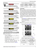
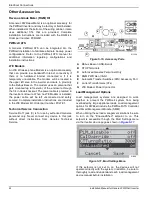
See
. The PWRcell inverter is equipped
with four AC grid connection terminals and three
protected loads terminals.
•
Use the top four terminals (A) for connection to the
utility grid.
NOTE:
Use L3 terminal (B) with 3-phase inverters only.
•
Use the bottom three terminals (C) for protected
loads output. See
.
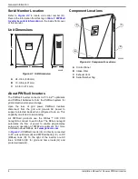
Figure 5-4. AC Wiring Terminals
(000686a)
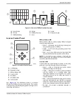
DANGER
Electrocution. Never touch terminals when
inverter and PWRcell DC disconnects are ON.
Doing so will result in death or serious injury.
(000646)
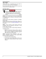
Equipment damage. Obey polarity markings when
connecting REbus devices. Reverse-polarizing DC
circuits could result in equipment or property damage.
WARNING
(000645)
WARNING
Equipment damage. Do not connect raw, unregulated
battery output to inverter. Connect only REbus-compatible
batteries. Connecting batteries that are not REbus-
compatible could result in equipment or property damage.
Equipment damage. Do not connect PV string output
directly to inverter. PV must be connected via Generac
PWRcell PV Link. Connecting PV output directly to inverter
could result in equipment or property damage.
CAUTION
(000644a)
(000647a)
CAUTION
Equipment damage. Connect only one wire to each
DC wiring terminal. Doubling wires on a terminal
could result in equipment or property damage.
Equipment damage. Connect only to REbus-compatible
devices to the DC bus. Never connect to any other DC
power source. Connecting to other DC power sources
could result in equipment damage.
(000598a)
CAUTION
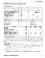
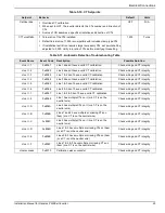
Table 5-6. DC Wiring Terminal Specifications
Wire Size
Terminal
Temp Range
Wire Min
Temp Rating
Torque
18-6 AWG
(.75-10 mm)
-40 to 266ºF
(-40 to 130ºC)
194ºF
90ºC
12 in-lb
(1.35 Nm)
•
Torque all terminals as specified in
Table 5-7. AC Wiring Terminal Specifications
Wire Size
10 to 6 AWG
(5.26 mm
2
to 13.3 mm
2
)
Terminal Temp Range
Up to 248ºF (120ºC)
Wire Min Temp Rating
194ºF (90ºC)
Torque
13.3 in-lb to 15.9 in-lb
(1.5 Nm to 1.8 Nm)
N1
L1
L2
N
Protcd.
L3
(3p)
L1
Protcd.
L2
Protcd.
C
009996
A
B


