Installation and Setup
076R176-000
SC SRM-6 Multiplexer
2-5
Issue 1
Installation & Operation Manual
Cable Connections
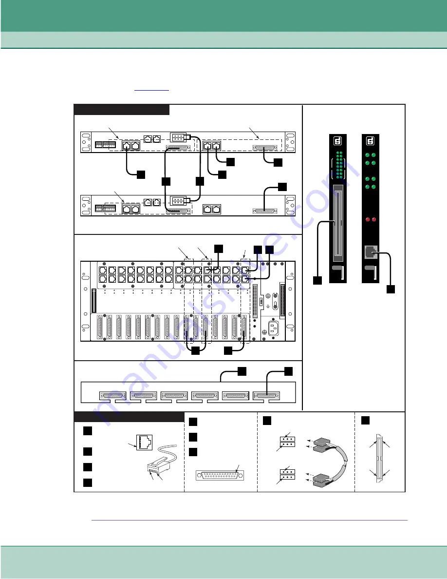
Front panels and shelf rear panels provide the interface connectors for management, DCE, and DTE
connections.
describes these connections and the associated cables and adapters.
Figure 2-2
Shelf and Card Connections (Shown: SC2000 and SC5000 Shelves)
SHELF#2
SCM 1
PIN 1
PIN 1
SCM 2
ON OFF
SCM
CTRL
SD
RD
SD
RD
NR
ND
TM ALM
INS
ON
L
A
N
W
A
N
SRM-6
INS
TM
ON
AM
SYNC
ET
1
2
3
4
5
6
SD
RD
J32
J48
J31
J47
J30
J46
J29
J45
J28
J44
J27
J43
J26
J42
J25
J41
J24
J40
J23
J39
J22
J38
J21
J37
J20
J36
J19
J35
J18
J34
J17
J33
J52
J14
J12
J11
J16
J15
J13
J10
J9
J8
J7
J6
J5
J2
J1
J4
J3
J51
J50
SC 5000 SHELF BACKPLANE
SC 2000 SHELF #1
BACK PANEL
A
MODEM
PRIVATE
LINE
REAR PANEL CONNECTIONS
FRONT PANEL DETAILS
MODEM/DSU to SRM-6
AGGREGATE PORT
B
PIN 8
PIN 1
J
G
CRAFT
PORT
SC 2000 SHELF #2
BACK PANEL
A
B
SCM
SRM-6
E
D
C
C
SCM
WAN
PIN
1
8
7
6
5
4
3
2
1
D
SCM
DBU WAN
PIN 1
SCM
LAN PORT
E
SHELF#1
F
BERG PIN CONNECTORS
(SC2000 shelf only)
D
C
E
B
J
SCM
CRAFT
G
MASS TERM
DCE CHANNEL
CONNECTOR
PIN
1
PIN
32
PIN
33
PIN
64
DCE
CHANNEL
CONNECTOR
CONNECTOR DETAILS
A
NOTES
In SC2000 installations, the SCM and modem
must be installed in the same shelf; the SRM-6
is installed in either slot of a second shelf.
In DDS and T1 applications, the SC21A/S or
SC553 DSU replaces the modem. Refer to the
corresponding manual to make rear panel
connections to those devices.
In a SC5000 shelf, install cards in any slot.
ACCESS PANEL
(MASS TERM DTE)
Port 1
Port 2
Port 3
Port 4
Port 5
Port 6
ACCESS PANEL
(WIRED DCE CHANNELS)
H
G
H
MODEM
(SLOT 2)
SCM
(SLOT 1)
SRM-6
(SLOT 4)
MODEM
SRM-6
SCM
B
SCM 1
F
PIN 1
PIN 1
SCM 2
ON OFF
MANAGEMENT
LINK CABLE
P1
P2
P3
P4
Summary of Contents for 076P054-001
Page 43: ......


