Installation
3.5 Initial Setup and Power-up
Detailed operating instructions for the DTR are provided in Section 4.0 of this
manual. The operator should become familiar with the general operating procedures
before continuing.
NOTE: Prior to powering the DTR, observe the incoming beacon signal
using a spectrum analyzer to ensure proper level (-110 dBm to -40 dBm)
and sufficient Carrier to Noise ratio (C/No) (35 dbHz minimum). Also,
make note of the beacon signal frequency. Then connect the RF input(s)
to the appropriate N-Type connectors and proceed with the following
steps.
1.
Set the DTR rear panel POWER switch to ON.
2.
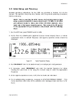
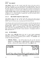
Verify that the 240x64-pixel graphical receiver status display shows a normal
operational mode. A default frequency and signal acquisition status should be
displayed.
Figure 3-2
Typical Operational Display
3.
Set
POL SELECT
item to the desired input (on multiple port configurations).
4.
If necessary, select
FREQUENCY
and enter the desired frequency by either
rotating the spin knob, or by using the numeric keys to enter the appropriate
frequency.
5.
Once signal acquisition occurs, verify that no faults are indicated.
6.
For troubleshooting assistance, navigate to STATUS\TROUBLE-SHOOT. This
menu describes what some of the possible error messages mean and how to fix
them.
CG-1220 DTR
3-11
Summary of Contents for CG-1220
Page 6: ...vi THIS PAGE INTENTIONALLY LEFT BLANK...
Page 10: ...Table of Contents x THIS PAGE INTENTIONALLY LEFT BLANK...
Page 16: ......
Page 54: ...Maintenance 5 4 CG 1220 DTR THIS PAGE INTENTIONALLY LEFT BLANK...
Page 56: ...Engineering Drawings 6 2 CG 1220 DTR THIS PAGE INTENTIONALLY LEFT BLANK...
Page 65: ...Appendix C DTR Remote M C Protocol CG 6073 Rev R Jun 2012 4 THIS PAGE INTENTIONALLY LEFT BLANK...
Page 130: ...Remote M C Protocol C 2 CG 1220 DTR THIS PAGE INTENTIONALLY LEFT BLANK...
Page 134: ...Acronyms Abbreviations D 4 CG 1220 DTR THIS PAGE INTENTIONALLY LEFT BLANK...


