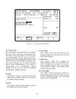
Mon Freq
Display of the actual monitored frequency.
Dev
Display of the frequency deviation in kHz.
Freq Err
The acquisition frequency error range is +1500
Hz as described for the RF Display.
Input Lvl
(Recall that Input Lvl is a short term average
not affected by the value selected for Slots.)
Errs
Display of the bit error count detected during
the test.
Bits
Display of the bit count during the test.
BER
Display of the ratio of bit errors to total bits
counted during the test. BER is displayed as a
percentage. The BER for one error in one
thousand bits is
00.1000%.
NOTE
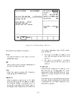
BER Meter measurement is accurate up to
20 percent bit errors.
Enabling the BER Test
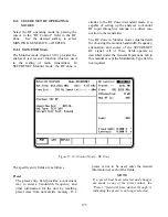
The BER test begins when BER meter is selected
in the Display Zone "Meter:" field.
Resetting the BER Test
To reset the BER test, move cursor to the
"Meter:" field in the Display Zone and press
more until reset is displayed. Press reset and the
BER count is started over from zero.
13-10.2 CLEAR SCOPE Display
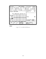
The CLEAR SCOPE display shows either the
received audio signal after it has been converted
to analog or the analog transmit signal before it is
digitized. To activate the CLEAR SCOPE, place
the analyzer in SECURENET mode. The
selection of either Monitor or Generate in the RF
Zone determines which signal will be displayed
on the screen. Press the DISP hardkey, place the
cursor in "Display:" field, and select the CLEAR
SCOPE softkey. The Display area of the screen
will indicate CLEAR SCOPE with the input sig-
nal displayed in a time-versus-amplitude graph.
figure 13-16 shows the display, cursor and
associated softkey used for the CLEAR SCOPE.
The operator can adjust the horizontal scale by
placing the cursor in "Horiz:" field and selecting
the appropriate value from the softkey selections.
To change the vertical scale, go to the "Vert:"
field and select the appropriate value from the
softkey selections.
13-10.2.1 Monitor Mode
In Monitor mode, the CLEAR SCOPE display
shows the recovered analog audio signal. The
CLEAR SCOPE operational controls are similar
to the Standard version MOD SCOPE except the
vertical scope is mv/div instead of kHz/div.
To change horizontal position, horizontal range,
vertical position, or vertical range, use the cursor
control keys to highlight the appropriate cursor
fields as follows:
Horiz
Press the desired softkey to select the Horizon-
tal Sweep rate (20
s to 1 sec/div).
Since all ranges cannot be shown on one
screen, press the
more
softkey for additional
selections.
185
Summary of Contents for R2600 Series
Page 8: ...3 7 1 3 AC DC Voltmeter 41 3 7 1 4 INT DIST EXT DIST Meter 43 v...
Page 46: ...This Page Intentionally Left Blank xxxvi...
Page 66: ...DISPLAY ZONE RF ZONE AUDIO ZONE Figure 3 1 Screen Zone Arrangement 20...
Page 68: ...Figure 3 2 System Help 22...
Page 83: ...Figure 3 11 General Sequence Mode Select 37...
Page 85: ...39 Figure 3 12 RF Display Zone...
Page 88: ...Figure 3 14 Digital Voltmeter Screens 42...
Page 102: ...Figure 3 22 Bar Graphs 56...
Page 107: ...Figure 3 24 Memory Screens 61...
Page 128: ...This Page Intentionally Left Blank 82...
Page 202: ...This Page Intentionally Left Blank 156...
Page 205: ...Figure 11 1 R 2670 with SECURENET Option Housing 159...
Page 206: ...This Page Intentionally Left Blank 160...
Page 218: ...Figure 13 8 Test Key Programming Display Figure 13 9 External Key Programming Display 172...
Page 225: ...Figure 13 12 Duplex Mode Display Zone 179...
Page 234: ...VOICE Figure 13 17 CLEAR SCOPE Markers 188...
Page 236: ...This Page Intentionally Left Blank 190...
Page 249: ...Figure 14 8 SECURENET CLEAR SCOPE Display of Output Modulation 203...
Page 252: ...This Page Intentionally Left Blank 206...
Page 256: ...210 This Page Intentionally Left Blank...
Page 267: ...Figure 17 7 Encryption Select Display Figure 17 7 Encryption Select Display 221 221...
Page 286: ...This Page Intentionally Left Blank 240...
Page 291: ...Figure 18 1 Radio BER Test Mode Audio Zone Figure 18 2 Radio BER Test Mode BER Meter 245...
Page 293: ...Figure 18 4 Receive BER 247...
Page 298: ...Figure 18 6 ASTRO CLEAR SCOPE Display of Output Modulation 252...
Page 304: ...Figure 21 1 PROJ 25 Version Screen Figure 21 2 PROJ 25 Options Screen 258...
Page 309: ...Figure 21 6 SET UP Display Screen Figure 21 7 Encryption Select Display 263...
Page 335: ...Figure 22 4 PROJ 25 CONV CLEAR SCOPE Display of Output Modulation 289...
Page 339: ...Figure 24 1 PROJ 25 Version Screen Figure 24 2 PROJ 25 Options Screen 293...
Page 354: ...Figure 25 3 Encryption Select Display Figure 25 4 Algorithm Select Display 308...
Page 369: ...B 6 This Page Intentionally Left Blank...
Page 379: ...This Page Intentionally Left Blank F 4...
Page 383: ...This Page Intentionally Left Blank H 2...
Page 389: ...J 4 This Page Intentionally Left Blank...
Page 393: ...This Page Intentionally Left Blank K 4...

