background image

Appendix L 

PROJECT 25 ERROR AND WARNING MESSAGES 


L-1 ERRORS 

 
Project 25 errors fall into two categories: 
EMC/Encryption Key Errors and Project 
25 Errors.  Error messages are defined 
as: “Messages displayed to alert the user 
to failures which affect system or test 
functionality.”  A summary of 
EMC/Encryption Key and PROJ 25 
Errors follows. 
 

L-1.1 EMC/Encryption 

Error 

Messages 
 

The following errors occur when there 
has been an error or failure that prevents 
encryption decode or encode from 
operating correctly.  The probable cause 
for the error, along with a recommended 
solution is presented. 

(qwdId: quick, what do I do?) 


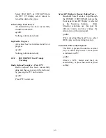
Hardware Failure- Perform Encrypt 
Reset 


This message indicates that the 
Hardware Encryption Modules have 
failed.  The system has either been 
unable to communicate with one or 
both of the modules or the module 
has indicated that is has experienced 
a startup error. 

 
 qwdId: 
 
 Perform 

encrypt reset

 from the 


Special Function window.  If the 


problem persists, contact the Service 

 Representative. 


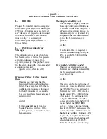
Warning-External Key Lost 


This message is displayed when a 


Powerup Configuration Failure has 


occurred.  This is most likely due to 


a Password Validation Failure.  In 


this case, all previously stored keys 


and passwords have been erased as 


part of the hardware recovery 

 process. 
 
 qwdId: 


If an External Key is required, it 


must be reloaded using a DX type 


KVL or any KVL  3000 with the 

 ASN 

option. 


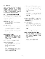
Key Invalid-Verify Key Loaded 


The user has attempted to use an 


External Key which is not available 


for  the selected algorithm or 

 encryption 

type. 

 
 qwdId: 


This error can be cleared in one of 


two ways.  You can either test using 


the TEST KEY or you can load an 


External Key using a DX type key 


loader, or any KVL 3000 with the 


ASN option.  To continue testing 


using the TEST KEY, select the 


correct algorithm from the SET UP 


menu.  Select the 

TEST KEY 


softkey.  To test using the External 


Key in the SET UP menu, select the 


correct algorithm and then select the 


load ext key 

softkey.  Connect a DX 


key loader, or any KVL 3000 with 


the ASN option, which matches the 


selected algorithm to the R625.  


Enter the desired key into the key 

Summary of Contents for R2600 Series

Page 1: ...GENERAL DYNAMICS R2670 R2625 Series Communications System Analyzer OPERATOR S MANUAL CG 1089 Rev A...

Page 2: ...CG 1089 Rev A R2670 R2625 Series Communications System Analyzer OPERATOR S MANUAL GENERAL DYNAMICS...

Page 3: ...670 R2625 Series Communications System Analyzer OPERATOR S MANUAL GENERAL DYNAMICS SATCOM TECHNOLOGIES Communications Test Equipment 3750 W Loop 281 Longview TX 75604 COPYRIGHT 2009 GENERAL DYNAMICS A...

Page 4: ...s 1 1 2 4 Explosive Atmosphere 3 1 2 SICHERHEITSHINWEISE 2 1 2 1 Funkme platz erden 2 1 2 2 Das Ger t steht auch in ausgeschaltetem Zustand unter Spannung 2 1 2 3 Vorsicht vor spannungsf hrenden Teile...

Page 5: ...nstige Vorsichtsma nahmen 8 1 3 6 Ersatz und Entsorgung von Akkus 8 1 3 7 Reinigung 8 1 4 SERVICE7 1 4 KUNDENDIENST 8 1 5 REPLACEMENT PARTS ORDERS 7 1 5 ERSATZTEIL BESTELLUNGEN 8 1 6 INSTALLATION 7 1...

Page 6: ...age 2 1 DESCRIPTION 13 2 2 OPERATOR CONTROLS 13 2 2 1 Keys Indicators 13 2 2 2 Knobs 17 2 2 3 DISPLAY 17 2 2 4 Connectors 17 2 2 4 1 Front Panel Connectors 17 2 2 4 2 Side Panel Connectors 18 2 2 4 3...

Page 7: ...21 3 2 2 3 Dedicated Keys 21 3 3 HELP 21 3 4 WARNINGS 23 3 5 PRIMARY OPERATING MODES 24 3 5 1 MONITOR Mode 24 3 5 1 1 Phase Modulation 25 3 5 2 GENERATE Mode 26 3 5 3 DUPLEX Mode 28 3 5 4 SWEEP GENER...

Page 8: ...3 7 1 3 AC DC Voltmeter 41 3 7 1 4 INT DIST EXT DIST Meter 43 v...

Page 9: ...if equipped 47 3 7 2 Display 49 3 7 2 1 Spectrum Analyzer 49 3 7 2 2 Modulation Scope 52 3 7 2 3 EXT L SCOPE 55 3 7 2 4 SWEEP GENERATE 55 3 7 2 5 Bar Graphs 55 3 7 2 6 Tracking Generator if equipped 5...

Page 10: ...EIVER TESTING 69 4 2 1 Basic FM Receiver Testing Setup 70 4 2 2 Receiver Distortion Measurement 71 4 2 3 SINAD Measurement 71 4 2 4 Modulation Acceptance Bandwidth 72 4 2 5 Receiver Sensitivity Testin...

Page 11: ...Table of Contents CONT Section 5 TRUNKING INTRODUCTION Topic Page 5 1 INTRODUCTION 83 5 2 CAPABILITIES 83 5 3 WHAT IS TRUNKING 84 5 3 1 Trunk Signaling Types 85 viii...

Page 12: ...91 6 6 1 Radio Initiated Dispatch Trunk I Testing 91 6 6 2 RF ZONE 93 6 6 3 Radio Initiated Dispatch Trunk I EP II Testing 97 6 6 4 Radio Initiated Dispatch Trunk II Testing 97 6 6 5 Radio Initiated D...

Page 13: ...quence Trunk I and Trunk I EP II Signaling 117 7 3 2 Radio Initiated Phone Interconnect Test Sequence Trunk II Signaling 119 7 3 3 System Initiated Phone Interconnect Test Sequence Trunk I and Trunk I...

Page 14: ...Table of Contents CONT Section 8 ASTRO TRUNKING INTRODUCTION Topic Page 8 1 INTRODUCTION 133 8 2 CAPABILITIES 133 xi...

Page 15: ...runking Testing 138 9 4 2 Spectrum Analyzer Dispersion Limit While in Trunked Test Mode 138 9 4 3 Remote Operation 138 9 5 ACCESSING TRUNK MODE 139 9 6 RADIO INITIATED TRUNKING 139 9 6 1 Radio Initiat...

Page 16: ...Radio Initiated Dispatch Test Astro Signaling 147 10 2 2 System Initiated Dispatch Test Astro Signaling 149 10 3 CALL ALERT TESTING 151 10 3 1 Radio Initiated Call Alert Test Astro Signaling 151 10 3...

Page 17: ...Table of Contents CONT Section 11 ASTRO TRUNKING INSTRUCTIONS Topic Page 11 1 INTRODUCTION 157 11 2 CAPABILITIES 157 11 3 SECURENET OPTION HOUSING 158 11 3 1 Description 158 11 3 2 Connectors 158 xiv...

Page 18: ...xv Table of Contents CONT Section 12 SECURENET DESCRIPTION Topic Page 12 1 INTRODUCTION 161 12 2 BASIC OPERATION 161 12 3 TEST CONSIDERATIONS 161 12 4 SPECIAL TERMS 161...

Page 19: ...167 13 5 TEST SETUP 168 13 5 1 Connecting a Radio 168 13 6 ACCESSING SECURENET MODE 169 13 7 SECURENET ENCRYPTION SET UP 170 13 7 1 SET UP Encrypter Display 170 13 7 1 1 Algorithm Select 170 13 7 1 2...

Page 20: ...3 9 1 2 External 180 13 9 2 Voice Encode 180 13 9 2 1 Monitor Mode 180 13 9 2 2 Generate Mode 181 13 9 3 BER Encode 183 13 9 3 1 Monitor Mode 183 13 9 3 2 Generate Mode 183 13 9 3 3 Duplex Mode 183 13...

Page 21: ...TING THE RADIO TRANSMITTER Monitor mode 193 14 3 1 Radio in BER Test Mode 193 14 4 BER TESTING USING DUPLEX MODE 195 14 4 1 Radios without BER Test Capability 196 14 4 2 Radios With BER Test Capabilit...

Page 22: ...Table of Contents CONT Section 15 ASTRO OPTION INTRODUCTION Topic Page 15 1 INTRODUCTION 207 15 2 CAPABILITIES 207 15 3 ASTRO OPTION HOUSING 207 15 3 1 Description 207 15 3 2 Connectors 208 xix...

Page 23: ...xx Table of Contents CONT Section 16 ASTRO OPTION DESCRIPTION Topic Page 16 1 INTRODUCTION 211 16 2 BASIC OPERATION 211 16 3 TEST CONSIDERATIONS 211 16 4 SPECIAL TERMS 211...

Page 24: ...ION CAPABILITIES 217 17 5 TEST SETUP 217 17 5 1 Connecting a Radio 217 17 6 ACCESSING ASTRO MODE 219 17 7 ASTRO ENCRYPTION SET UP 220 17 7 1 SET UP Encryption Display 220 17 7 1 1 Encrypt 220 17 7 1 2...

Page 25: ...erate Mode 230 17 9 3 Voice Frame Embedded Signaling Generate 232 17 10 BER 233 17 10 1Monitor Mode 233 17 10 2Generate Mode 233 17 10 3Duplex Mode 234 17 11 ASTRO METER AND DISPLAY CONTROL 235 17 11...

Page 26: ...2 1 ASTRO Voice 242 18 2 2 ASTRO Embedded Data 242 18 3 ASTRO RADIO RECEIVE TESTS 243 18 4 BER TESTING THE RADIO RECEIVER Generate Mode 243 18 5 BER TESTING THE RADIO TRANSMITTER Monitor mode 244 18 6...

Page 27: ...Table of Contents CONT Section 19 PROJECT 25 INTRODUCTION Topic Page 19 1 INTRODUCTION 253 19 2 CAPABILITIES 253 19 3 PROJECT 25 CONNECTORS 253 xxiv...

Page 28: ...Table of Contents CONT Section 20 PROJECT 25 DESCRIPTION Topic Page 20 1 INTRODUCTION 255 20 2 BASIC OPERATION 255 20 3 TEST CONSIDERATIONS 255 20 4 SPECIAL TERMS 255 xxv...

Page 29: ...260 21 3 6 HELP 260 21 4 ENCRYPTION CAPABILITIES 260 21 5 TEST SETUP 260 21 6 ACCESSING PROJ 25 MODE 261 21 7 PROJ 25 ENCRYPTION SET UP 262 21 7 1 SET UP Encryption Display 262 21 7 1 1 Encrypt 262 21...

Page 30: ...1011 Hz Tone Test Pattern 272 21 9 3 1 Monitor Mode 272 21 9 3 2 Generate Mode 273 21 9 4 Calibration Test Pattern 274 21 9 4 1 Generate Mode 274 21 9 5 Silence Pattern 274 21 9 5 1 Generate Mode 274...

Page 31: ...ing 280 22 2 PROJ 25 RADIO TRANSMIT TESTS 281 22 2 1 PROJ 25 Voice 281 22 2 2 PROJ 25 Voice Frame Embedded Data 281 22 3 PROJ 25 RADIO RECEIVE TESTS Generate Mode 282 22 4 BER TESTING THE RADIO RECEIV...

Page 32: ...Table of Contents CONT Section 23 PROJECT 25 TRUNKING INTRODUCTION Topic Page 23 1 INTRODUCTION 290 23 2 CAPABILITIES 290 23 3 PROJECT 25 CONNECTORS 290 xxix...

Page 33: ...Remote Operation 295 24 3 6 Help 295 24 4 PROJ 25 TRUNK MODE 295 24 4 1 Registration Call Alert 296 24 4 2 Dispatch Voice 296 24 4 3 PROJ 25 Trunking Screens 297 24 4 3 1 Display Zone 297 24 4 3 2 RF...

Page 34: ...ption Display 307 25 3 1 1 Encrypt 307 25 3 1 2 Algorithm Select 307 25 3 1 3 Key Type 309 25 3 1 4 Encrypt Self Test 309 25 3 2 Using the Test Key 309 25 3 3 Programming with External Key 309 25 3 3...

Page 35: ...LOG TRUNKING OPTION ISW CALL TYPE DESCRIPTION F 1 Appendix G ASTRO TRUNKING ERROR AND WARNING MESSAGES G 1 Appendix H ASTRO TRUNKING TEST SEQUENCE CODE DESCRIPTION H 1 Appendix I ASTRO TRUNKING OPTION...

Page 36: ...e 3 6 Generate Mode 26 Figure 3 7 Duplex Mode 28 Figure 3 8 Sweep Generator Mode 30 Figure 3 9 Tracking Generator Mode 32 Figure 3 10 PL Format Selection 35 Figure 3 11 General Sequence Mode Select 37...

Page 37: ...e 6 8 Dispatch Test Screen System Init Trunk II Signaling 102 Figure 6 9 Radio Configuration Screen Trunk I and Trunk I EP II 103 Figure 6 10 Radio Configuration Screen Trunk II 105 Figure 6 11 Radio...

Page 38: ...Test Mode BER Meter Sample 194 Figure 14 3 Transmit BER 195 Figure 14 4 Receive BER 196 Figure 14 5 Basic FM Receiver Testing Setup 198 Figure 14 6 Basic FM Transmitter Testing Setup 199 Figure 14 7 S...

Page 39: ...isplay 239 Figure 18 1 Radio BER Test Mode Audio Zone 245 Figure 18 2 Radio BER Test Mode BER Meter 245 Figure 18 3 Transmit BER 246 Figure 18 4 Receive BER 247 Figure 18 5 ASTRO CLEAR SCOPE Display o...

Page 40: ...ered Audio 287 Figure 22 4 PROJ 25 CLEAR SCOPE Display of Output Modulation 289 Figure 23 1 Bottom of R2670 291 Figure 24 1 PROJ 25 Version Screen 293 Figure 24 2 PROJ 25 Option Screen 293 Figure 24 3...

Page 41: ...System Initiated Dispatch Testing 114 Table 7 6 Trunk I EP II Signaling Events System Initiated Dispatch Testing 114 Table 7 7 Trunk II Signaling Events System Initiated Dispatch Testing Without Auto...

Page 42: ...tro Signaling Events System Initiated Testing With Auto Affiliation 151 Table 10 5 Astro Signaling Events Radio Initiated Call Alert Testing Without Auto Affiliation 152 Table 10 6 Astro Signaling Eve...

Page 43: ...assembly with a new or reconditioned replacement This Limited Warranty is not extended beyond one year from original date of shipment if General Dynamics repairs a product Transportation charges for t...

Page 44: ...ve the option of refunding the purchase price or replacing the SOFTWARE as LICENSEE S exclusive remedy 5 LIABILITY THIS WARRANTY IS EXCLUSIVE AND IN LIEU OF ALL OTHER WARRANTIES WHETHER STATUTORY EXPR...

Page 45: ...ntre Unit 10 18 F Kodak House II 39 Healthy Street East North Point Hong Kong Ph 852 2590 4800 Fax 852 2590 7950 SINGAPORE Motorola Electronics Pte Ltd 10 Ang Mo Kio Street 65 01 01 Tech Point Buildin...

Page 46: ...This Page Intentionally Left Blank xxxvi...

Page 47: ...equipment in your operating environment 1 2 1 Grounding the Analyzer To minimize shock hazard the Analyzer enclosure must be connected to an electrical ground This ground connection is provided via a...

Page 48: ...1 Funkme platz erden Zur Verringerung der Gefahr eines elektrischen Schlages mu das Ger t elektrisch geerdet werden Die Sicherheitserdung erfolgt ber das dreiadrige Netzkabel Der Netzstecker mu dazu...

Page 49: ...ts take proper precautions in handling should the need arise Refer to Appendix C for safe handling procedures 1 3 1 Analyzer Operating Voltage Before plugging in an AC power cable verify that the sele...

Page 50: ...en zu beachten Einzelheiten dazu gehen aus Anhang C hervor 1 3 1 Betriebsspannung Vor dem Anschlu des Funkme platzes an das Netz ist sicherzustellen da am Spannungsw hler auf der Unterseite des Ger te...

Page 51: ...115 230 VAC L 250V 2 5A F 65 P30222C003 Rear Panel 115 230 VAC N 250V 2 5A F 65 P30222C003 Front Panel ANT 125V 1 16A F 65 P30277C002 Front Panel GEN 125V 1 16A F 65 P30277C002 Table 2 Internal Fuses...

Page 52: ...CHERUNGSWERTE VOLT AMP TYP TEILENUMMER R ckwand 115 230 VAC L 250V 2 5A F 65 P30222C003 R ckwand 115 230 VAC N 250V 2 5A F 65 P30222C003 Frontplatte ANT 125V 1 16A F 65 P30277C002 Frontplatte GEN 125V...

Page 53: ...include the complete identification number located on the equipment Also direct inquiries to the Test Equipment Service Center including requests for part number identification and test equipment cali...

Page 54: ...tes an das n chstgelegene Motorola Test Equipment Service Center zu richten Hier erhalten Sie auch Antwort auf Ihre Fragen bez glich Teilenummern Kalibrierung und Reparatur von Testger ten 1 6 INSTALL...

Page 55: ...perating procedures described in this manual CAUTION NOTE When installing the Analyzer in a vehicle fuse the DC supply line close to the vehicle s battery The DC 10A fuse located on the Analyzer s rea...

Page 56: ...atz Der als Option erh ltliche Akkusatz RPN 4000A l t sich bequem an der R ckseite des Funkme platzes anflanschen Da der Akkusatz ber ein integriertes Ladeger t verf gt wird er automatisch aufgeladen...

Page 57: ...ons of the power plug on the Analyzer Do not engage the attach ment screw yet 3 Plug four pin connector from battery pack to four pin connector on back of Analyzer labeled DC POWER 4 Plug AC cord from...

Page 58: ...anziehen 3 Verbinden Sie den vierpoligen Anschlu stecker des Akkusatzes mit dem vierpoligen Anschlu DC POWER auf der R ckseite des Funkme platzes 4 Stecken Sie das Netzkabel des Akkusatzes in den Netz...

Page 59: ...Strength Meter SINAD Meter Distortion Analyzer 2 2 OPERATOR CONTROLS 2 2 1 Keys Indicators Power Switch Press ON to energize all circuitry The unit automatically selects AC power if line power is avai...

Page 60: ...ER DC BRIGHT 7 8 9 4 5 6 2 3 ALT 0 1 F1 SPF PRT CAL VOLUME SQUELCH CURSOR ZONE CURSOR POSITION DISP RF AUD TAB HELP MEM RF IN OUT CAUTION 125W MAX GEN OUT CAUTION DO NOT INPUT POWER VERT SINAD DIST DV...

Page 61: ...tom Panels RS 232 PORT 10 MHZ REFERENCE OSCILLATOR IN OUT DC INPUT PWR CONNECTOR AC PLUG FUSES INTERNAL EXTERNAL REFERENCE OSCILLATOR SWITCH REFERENCE OSCILLATOR CALIBRATION ADJUST LINE VOLTAGE SELECT...

Page 62: ...functions on the keypad Upon pressing the ALT key the message ALT appears on the message line Pressing any other key following the ALT key will cause the ALT message to disappear SPF Key Displays the...

Page 63: ...ectors RF IN OUT Provides RF input signal to the analyzer s internal monitor or output signal from the analyzer s internal generator Also provides combined in put output in DUPLEX mode Contains the RF...

Page 64: ...nt is 70 mV to 1 Vrms Output level is approximately 250 uVrms AC POWER Connector Primary AC power input port DC POWER Connector Primary DC power input port 2 3 BOTTOM CONTROLS Internal External Oscill...

Page 65: ...hesizer and level selection for externally applied modu lation are provided through the Audio area at the lower right of the screen Further explanation of the function of each of these screen areas ca...

Page 66: ...DISPLAY ZONE RF ZONE AUDIO ZONE Figure 3 1 Screen Zone Arrangement 20...

Page 67: ...its original size 3 2 2 2 Display Tables Decode Tables are selected from the Meter field Selection of General Sequence 5 6 Tone or Select V decode modes causes the system to overwrite the meter and d...

Page 68: ...Figure 3 2 System Help 22...

Page 69: ...e Low If any of these conditions exist A warning will be displayed on the warning line of the LCD for RF overload recalibrate and low battery voltage A continuous audible warning tone along with an ov...

Page 70: ...R Mode The Monitor mode figure 3 4 provides the analyzer s test receiver function which is used in the testing of radio transmitters It is capable of monitoring RF input through it s antenna or a dire...

Page 71: ...the unit s sensitive receiver and should be used with an antenna for off the air reception Selection of the ANT port is indicated by a red LED adjacent to the ANT connector CAUTION Do not apply input...

Page 72: ...le output level to provide for a wide range of receiver testing Multiple internal andexternal modulation signals can be simultaneously impressed on the carrier frequency to generate composite signals...

Page 73: ...the high level GEN output port is selected The range of 130 dBm to 50 dBm is avail able when the RF I O output port is selected NOTE If AM modulation is selected the maximum output at the GEN port is...

Page 74: ...output that is offset in frequency from the monitor center frequency and fully adjustable in output level This capability provides for servicing full duplex radio equipment as well as repeaters and r...

Page 75: ...constrained to 000 40000 MHz through 999 99995 MHz The offset frequency is set in 2 5 kHz steps Mon This field actually contains two separate fields one for monitor input attenuation and one for moni...

Page 76: ...er test To facilitate display of swept responses of networks under test the units built in scope display can be accessed by selecting SWEEP GENERATE within the Display field A suitable RF detector pro...

Page 77: ...e as follows Rng Selects the RF frequency range over which the generator will sweep Specific ranges are selectable via softkeys Rate Selects the sweep rate for the generator and corresponding scope di...

Page 78: ...test Connect the output of the network under test to the ANT port Be sure to activate the ANT port thru the Mon field in the RF Control zone If input attenuation is needed as part of the mea surement...

Page 79: ...red display depending on the type of network being tested Rng Selects the RF frequency range over which the generator will sweep These are expressed in full screen deflection ranges that are selectabl...

Page 80: ...ff the modulation source Off is indicated by an X at the extreme right adjacent to the level BURST provides a single timed sequence of modulation only for DTMF TONE A TONE B 5 6 TONE A B SEQUENCE GENE...

Page 81: ...oftkey selects a number of international formats for five tone sequential signaling This selection produces two additional fields on the Code line below the Format Sel field The first allows a choice...

Page 82: ...ding to a given code number i e 1 2 3 etc Frequency and times are each selected inde pendently This is done through entry of inde pendent Code Sequence and Dur Sequence for example Code 1 may be selec...

Page 83: ...Figure 3 11 General Sequence Mode Select 37...

Page 84: ...The display of metered data is presented both digitally and graphically within the Display zone in the left portion of the screen figure 3 12 This zone is divided into two separate display areas Mete...

Page 85: ...39 Figure 3 12 RF Display Zone...

Page 86: ...rol zone this location will display in radians Dev AM Indicates the modulation level of the received carrier dependent upon the modulation type selected in the RF Control zone If the receive phase mod...

Page 87: ...indicates scanning When a carrier is acquired this changes to metering The actual measured frequency is displayed in the Meter zone along with modulation and level data as des cribed above for RF Dis...

Page 88: ...Figure 3 14 Digital Voltmeter Screens 42...

Page 89: ...ssed via softkey through the Meter field within the Display zone Their inputs are all normally internally coupled to the monitor demodulated signal for either direct or off the air testing If use of t...

Page 90: ...the right of the display is an indication of when gating occurs This softkey provides decoding for valid Motorola Digital Private Line DPL codes Refer to Appendix B for applicable codes Selection of...

Page 91: ...or mis termination The cable fault feature is accessed by softkey from the Meter field location in the Display zone as shown in figure 3 16 This automatically selects the appropriate displays in the R...

Page 92: ...he decoding function SEL V Decode This softkey provides a decoding function for a number of standard international Select V sequential tone signalling formats Selection of this mode overwrites the ent...

Page 93: ...emporarily skip past a channel with heavy radio traffic When the analyzer is locked on a preset frequency and you wish to continue scanning although the signal is preset press the PRESET SCAN softkey...

Page 94: ...nd the analyzer will not stop and dwell on the channel To adjust the squelch control for proper scanning operation turn the squelch control fully counterclockwise and activate the Preset Scan mode The...

Page 95: ...RF I O port may be selected for input from the RF Control zone The amount of input attenuation may also be selected within the zone to vary the sensitivity of the Spectrum Analyzer If a larger displa...

Page 96: ...ssing this softkey provides immediate storage of a spectrum display This allows cap ture of intermittent transmissions etc for more detailed analysis To return to normal real time analysis simply pres...

Page 97: ...pon the information displayed on the graph These controls are available for both the DELTAT and ABS marker selections by pressing the more softkey max peak Find the maximum peak on the graph right pea...

Page 98: ...that the trigger level be set to 500 and the triggering be set to AUTO To change triggering horizontal position horiz ontal range vertical position or vertical range use the cursor control keys to hig...

Page 99: ...MOVE RIGHT or by using the rotary TUNING knob Vertical Sensitivity Press the desired softkey to select the Vertical Sensitivity AM 1 to 50 per division FM 100 Hz to 50 kHz per division dependent on b...

Page 100: ...hows the relative horizontal deflection between the two marker positions in units of time This softkey selection provides markers that are also vertically located to permit relative readings along the...

Page 101: ...the optional cable fault test feature Refer to Sweep Generator description under Primary Operating Modes paragraph 3 5 4 To change coupling from AC to DC or vary horizontal position vertical position...

Page 102: ...Figure 3 22 Bar Graphs 56...

Page 103: ...r ature extremes and aging Re calibration is recommended at weekly intervals or when the re calibrate warning appears on the screen CAUTION Before starting self calibration be sure that the 50 ohm loa...

Page 104: ...ire RF Preset memory area and front panel CAL memory The Analyzer must be recalibrated after this key has been pressed 3 8 4 Special Functions Menu The Special Function mode figure 3 23 ac cessed by p...

Page 105: ...nt panel connector Internal External Input Decoding Switches the decoder function between the internal monitor demodulated signal and the signal at the VERT SINAD front panel con nector Display Timeou...

Page 106: ...s the MEM key to access the special Memory screen 2 Move the cursor to the desired preset num ber When the cursor is over the preset number press the view preset softkey to display all of the preset s...

Page 107: ...Figure 3 24 Memory Screens 61...

Page 108: ...factory NOTE The default Test Setup values are provided as a convenience and may be overridden at any time Each Test Setup also saves the cursor location for later recall For example if the analyzer...

Page 109: ...eset cursor location in the RF Control Zone Each Test Setup has a 15 character label in which alpha numeric information can be entered to describe that Test Setup Characters not on the front panel key...

Page 110: ...zers General Dynamics takes no responsibility for application accuracy applicability or safety Always refer to your own transceiver s service manual for recommended test methods and spec ifications IN...

Page 111: ...ph 3 4 4 1 2 Transmit Power Frequency and Frequency Deviation Measurements 1 With the cursor located within the RF Control zone refer to paragraph 3 2 press the MON softkey to place the analyzer into...

Page 112: ...eviation errors install the internal 300 Hz lowpass filter as detailed in paragraph 3 8 5 before making the following measurements and verifications 2 When monitoring the PL or DPL deviation as follow...

Page 113: ...um rated system deviation to determine if any adjustments are required Meter RF DISPLAY Mon Freq 816 500 MHz Freq Err 47 Hz Dev 3 5 kHz Input Lvl 70 5 dBm 6 Set the 1 kHz audio modulating signal for m...

Page 114: ...Set the SQUELCH control to threshold Within the RF Control zone set as follows RF Control Preset B W NB MONITOR Freq Attenuation 20 dB 816 5000 MHz Mon RF In ANT Modulation Type FM Transmitter Carrie...

Page 115: ...the analyzer The analyzer s DVM input is unbalanced ground referenced Use an appropriate interface to measure balanced circuits such as certain receiver audio outputs or telephone lines IN OUT GEN OUT...

Page 116: ...el 112 dB 816 5000 MHz Mon RF In RF I O Modulation Type FM Receiver Frequency NOTE For setup and distortion measurements set output level to at least 30 dB above sensitivity threshold 80 dBm recommend...

Page 117: ...rsor located within the Display Control zone press the EXT DIST softkey to measure percentage of distortion INT DIST EXT DIST SINAD more External Distortion 2 Refer to the displayed digital readout an...

Page 118: ...RF output level can be referenced to mV uV dBu or dBm Selection of units is available within the Display Control zone Output Level 4 Read the deviation level required in step 3 A typical modulation ac...

Page 119: ...zone press the GEN softkey MON GEN DUPLEX Generator Mode Softkey 5 Within the Audio Control zone set the modulation off Mod Sum 0 00 kHz Fixed 1kHz Synth 3 00 kHz 7 kHz Format Sel DPL Code 021 DTMF 0...

Page 120: ...Control zone set the modulation off 5 Within the RF Control zone increase the RF output level until the receiver just unsquelches This is the threshold squelch sensitivity of the radio 5 dB 816 5000...

Page 121: ...the Audio Control zone turn on the modulation and set the analyzer synthesizer to provide a nominal 750 Hz 500 1 kHz deviation or to the radio s manufacturer s specifications Mod Sum 0 00 kHz Fixed 1k...

Page 122: ...RF TEE 09 82578B01 RF OUTPUT RTL 4075A RF DETECTOR Figure 4 3 Basic Cable Testing Setup 4 3 2 Measuring Fault Distance Refer to figure 4 3 Connect the output of the RF Detector Probe RTL 4075A to the...

Page 123: ...ve pattern RF Control Rng 5 Mhz Rate 100 SWEEP GEN Cen Freq Output Lvl 00 0 dBm 816 5000 MHz Gen RF Out GEN Adjust as required Adjust as required Adjust as required NOTE This measurement generally wor...

Page 124: ...n Freq press the FIRST NULL softkey to display the frequency of the first null FIRST NULL Meter CABLE FAULT Cen Freq 816 5000 MHz Vel Const 0 6600 First Null 816 5000 MHz 7 With the cursor still locat...

Page 125: ...analyzer can simulate the tones and appear to the base station or repeater as a console or desk remote The most common use for the tone remote feature is commanding tone remote bases in order to meas...

Page 126: ...ol zone press the MON softkey to place the analyzer into its Monitor mode of operation MON GEN DUPLEX Monitor Mode Softkey 2 Tone Remote frequencies are programmed via the Tone A and Tone B memory Set...

Page 127: ...z Dev 3 5 kHz Input Lvl 70 5 dBm CONT x OFF BURST 4 5 Analyzer Setup for Printing The analyzer must use null modem cable to properly print with any serial printer Do not use a standard serial cable it...

Page 128: ...This Page Intentionally Left Blank 82...

Page 129: ...ual the system refers to the fixed end central controller Thus a system initiated call is the analyzer simulating the central controller calling the radio under test 5 2 CAPABILITIES Trunking option c...

Page 130: ...ver the local phone system Call Alert The analyzer supports the testing of call alert service The analyzer simulates the signaling for the radio to initiate or to receive a call alert Failsoft The ana...

Page 131: ...ual radio units contain preprogrammed fleet subfleet and unit ID information The code plug of each radio in a particular system contains this pre programmed information Also included in the code plug...

Page 132: ...ne or more talk groups Trunk II signaling also has eliminated the high speed handshake sequence on the voice channel Some Trunk II radios have an automatic affiliation option Auto affiliation allows a...

Page 133: ...uminated 6 1 INTRODUCTION The R2670 Digital Communications System Analyzer is an enhancement of the R2600 Series Communications System Analyzer Refer to sections 5 6 and 7 of the General Operation sec...

Page 134: ...E CURSORPOSITION DISP RF AUD TAB HELP MEM RFIN OUT CAUTION 125WMAX GEN OUT CAUTION DONOT INPUT POWER VERT SINAD DIST DVM COUNTERIN DEMOD OUT MOD OUT EXT MOD IN MIC COMMUNICATION SYSTEM ANALYZER 01 SOF...

Page 135: ...nking Analyzer Option Screen 6 4 GENERAL OPERATION The display screen is divided into three major zones 1 the Display Zone 2 the RF Zone and 3 the Audio Zone The top portion of Display Zone shows the...

Page 136: ...ectrum Analyzer Dispersion Limit While in Trunked Test Mode While the trunked test mode is active the spectrum analyzer maximum dispersion is limited to 1 MHz per division To use the higher dispersion...

Page 137: ...transmission from the radio is detected the analyzer will execute the test sequence defined by the parameters on the trunking screen In the following subsections the call sequence selected is Dispatch...

Page 138: ...ontrol keys to position the cursor and the softkeys to select the following parameters ID Disp ID Display is entered with the softkeys ID Display selects the format of the ISW data that is decoded The...

Page 139: ...ayed 6 6 2 RF ZONE Band Band selects the frequency channel plan for the analyzer Enter the Frequency Band with softkeys 800 MHz US Selection of the 800 MHz US band configures the analyzer for the freq...

Page 140: ...k 4 867 42500 868 97500 961 1022 25 45 800 MHz US Block 5 868 97500 958 25 45 Table 6 2 Available Transmit Frequency Ranges and Channel Plans 800 MHz Int l Frequency Range MHz Channel Range Channel Sp...

Page 141: ...corresponding frequency is dashed out Splinter channels can only be entered by frequency Standard channels can be entered by frequency or channel number channel numbers only map to standard channel f...

Page 142: ...he keypad or tuning knob When the channel number is changed the corresponding frequency value is changed If the channel number selected is out of range of the frequency channel plan the corresponding...

Page 143: ...r Throughout the handshaking sequence the trunking analyzer updates the status thermometer at the appropriate time Refer to Appendix F for a description of the status thermometer signaling events for...

Page 144: ...the other signaling types ID format the trunking analyzer will always display the ID information per the signaling type selected EXAMPLE If the radio is actually signaled with Trunk II yet its ID is d...

Page 145: ...naling Turn the radio on when the prompt message appears so it can lock to the control channel and register Successful registration will be indicated by seeing the squelch indicator LED flash briefly...

Page 146: ...so the radio can acquire the control channel After the time has elapsed the analyzer directs the radio to the voice channel and provides the voice channel handshake signaling required by the type of T...

Page 147: ...voice channel until the test is terminated To set up testing activate the Trunk mode per paragraph 6 5 place the cursor in the Meter field and press the softkey SYSTEM INIT to view current data and te...

Page 148: ...softkey TRUNK II to select Trunk II signaling A screen similar to figure 6 8 appears Figure 6 8 Dispatch Test Screen System Init Trunk II Signaling Parameter selection is similar to Radio Initiated Di...

Page 149: ...stem fleet map configurations can be stored in the analyzer With the Trunk mode activated per paragraph 6 5 place the cursor in the Sig Type field and press the softkey TRUNK I or TRUNK I EP II to sel...

Page 150: ...size code configuration of the system from the system manager Enter the system ID and the size code letters to the right of the system ID Enter the system configuration information before beginning a...

Page 151: ...0C08 Fleet ID 300 Fleet prefix 3 Individual ID 001 First enter the system ID number in the left hand column under System ID If the system has size codes AABBCCDD Enter these to the right of their cor...

Page 152: ...for each system in the VHF or UHF band Calls cannot be completed without correct entry of this data The data is obtained from the system manager It exists within the Code Management Data Base for eac...

Page 153: ...runking Frequency Information Example Control Channels MHz Channel Ranges Chan Spacing kHz Receive Transmit Start End 25 00 1 408 00000 413 00000 1 Rx 406 02500 409 00000 25 00 2 410 00000 415 00000 1...

Page 154: ...II VHF UHF Example Rx Block 1 covers the channels from 0 through 119 End Freq Start Freq Channel Spacing block base channel number 409 00000 MHz 406 02500 MHz 25 kHz 0 Rx Block 2 covers the channels...

Page 155: ...with ID Disp set for DEC the six digit Unit ID decoded from the ISW is the personality ID of the radio and not the unit ID When ID Disp is set for HEX the unit ID is displayed in hexadecimal The Fleet...

Page 156: ...ed Disconnect Tone Received on VC verifies the receipt of proper disconnect signaling X Disconnect Sent The trunking analyzer sent a disconnect word on the voice channel to end the call The radio will...

Page 157: ...x or voice channel number NOTE Splinter channels can only be entered by frequency Standard channels can be entered by frequency or channel number channel numbers only map to standard channel frequenci...

Page 158: ...Testing With Auto Affiliation SIGNALING EVENT DESCRIPTION D Affiliate ISW Received The trunking analyzer received the Affiliate ISW from the radio E Affiliate OSW Sent The trunking analyzer sends Aff...

Page 159: ...ID entered must match the system ID of the radio Otherwise the radio will not lock onto the control channel Refer to paragraph 6 8 Radio Configuration 3 Enter Fleet Subfleet and unit ID 4 Enter the C...

Page 160: ...annel X Disconnect Sent The trunking analyzer sent a disconnect word on the voice channel to end the call The radio will return to monitor the control channel Table 7 6 Trunk I EP II Signaling Events...

Page 161: ...atch the radio system ID and one of the system IDs in the Radio configuration screen in order to decode radio ID information 3 Enter Talk Group Call Type and Unit ID NOTE If an announcement call type...

Page 162: ...VENT DESCRIPTION D Affiliate ISW Received The trunking analyzer received the Affiliate ISW from the radio E Affiliate OSW Sent The trunking analyzer sends Affiliate OSWs on the control channel The Aff...

Page 163: ...port selection is RF I O with 50 dB for the level setting 6 Press the start test softkey The trunking analyzer generates an idle background pattern on the control channel and prompts the operator to...

Page 164: ...to use R HS Data Sent On VC At the same time as the Channel Grant the trunking analyzer sends high speed data on the voice channel U LS Word Sent On VC The trunking analyzer sends a low speed data wo...

Page 165: ...VCTx or voice channel number NOTE Splinter channels can only be entered by frequency Standard channels can be entered by frequency or channel number channel numbers only map to standard channel frequ...

Page 166: ...ING EVENT DESCRIPTION A Control Channel Idle The trunking analyzer outputs a background pattern on the control channel for the radio to lock onto D Affiliate ISW Received The trunking analyzer receive...

Page 167: ...the monitor attenuation and port selection Suggested port selection is RF I O with 20 dB attenuation 6 Set the generator attenuation and port selection Suggested port selection is RF I O with 50 dB f...

Page 168: ...t On VC The trunking analyzer sends a low speed data word on the voice channel Y Hangup Received The trunking analyzer decoded the Hangup ISW from the radio Table 7 14 Trunk I EP II Signaling Events S...

Page 169: ...tch the radio system ID and one of the system IDs in the Radio configuration screen in order to decode radio ID information 3 Enter talk group call type and unit ID NOTE If an announcement call type i...

Page 170: ...ALING EVENT DESCRIPTION A Control Channel Idle The trunking analyzer outputs a background pattern on the control channel for the radio to lock onto D Affiliate ISW Received The trunking analyzer recei...

Page 171: ...d by frequency Standard channels can be entered by frequency or channel number channel numbers only map to standard channel frequencies 4 Set the monitor attenuation and port selection Suggested port...

Page 172: ...and port selection Suggested port selection is RF I O with 20 dB attenuation 5 Set the generator attenuation and port selection Suggested port selection is RF I O with 50 dB for the level setting 6 P...

Page 173: ...T DESCRIPTION A Control Channel Idle The trunking analyzer outputs a background pattern on the control channel for the radio to lock onto D Affiliate ISW Received The trunking analyzer received the Af...

Page 174: ...Fleet Target Subfleet and Unit ID For the System Initiated Call Alert the Target Fleet Subfleet and Unit are the values for the radio under test If a radio initiated dispatch phone interconnect or cal...

Page 175: ...alyzer outputs a background pattern on the control channel to lock the radio J ISW Received The radio sent an Inbound Signaling Word ISW on the control channel to indicate the radio has been keyed P C...

Page 176: ...ID or Calling Unit ID simply move the cursor to the appropriate position and enter the new number In the system initiated test sequence the target Unit ID contains the data for the test radio while th...

Page 177: ...DESCRIPTION A Control Channel Idle The trunking analyzer outputs a background pattern on the control channel for the radio to lock onto D Affiliate ISW Received The trunking analyzer received the Aff...

Page 178: ...start test softkey If the parameters selected are not valid the test sequence is terminated and an error message is displayed When the start test softkey is pressed it is replaced with the stop test...

Page 179: ...nd central controller Thus a system initiated call is the analyzer simulating the central controller calling the radio under test 8 2 CAPABILITIES The trunking option has the following capabilities Vo...

Page 180: ...radio Test sequences can be performed on transmission trunked radios by pressing the PTT of the radio and keeping the radio keyed while switching to other display screens to make measurements and obse...

Page 181: ...eral Operation section of this manual for general installation in formation a description of the control functions and general operational information The following sections of this manual contain inf...

Page 182: ...CURSORPOSITION DISP RF AUD TAB HELP MEM RFIN OUT CAUTION 125WMAX GEN OUT CAUTION DONOT INPUT POWER VERT SINAD DIST DVM COUNTERIN DEMOD OUT MOD OUT EXT MOD IN MIC COMMUNICATION SYSTEM ANALYZER 01 SOFT...

Page 183: ...lyzer to generate a screen that displays the standard and option platform screens Move the cursor to the TRUNKING position and select the view options softkey A screen similar to the following screen...

Page 184: ...ed and the radio under test is on the voice channel other standard system screens may be entered from the Meter position of the Display zone Simply press the more softkey to cycle through the availabl...

Page 185: ...operator to initiate a transmission from the radio When a transmission from the radio is detected the analyzer will execute the test sequence defined by the parameters on the trunking screen In the f...

Page 186: ...exadecimal or decimal format Call Seq Call Sequence configures the trunking analyzer with the test sequence to be executed Dispatch Call Alert and Failsoft call sequences are supported in Astro signal...

Page 187: ...frequency or other parameters they may be accepted until a final validity check is done by the system at the time the start test softkey is pressed 9 6 3 RF ZONE Band Band selects the frequency chann...

Page 188: ...ue with softkeys The operator has the option of se lecting 0 20 or 40 dB attenuation Monitor Port Enter the port selection with softkeys In most cases the operator will set the monitor port to RF I O...

Page 189: ...hermometer at the appropriate time Refer to Appendix I for a description of the status thermometer signaling events for each test sequence The thermometer display progresses rapidly through the signal...

Page 190: ...ect the Trunk mode by placing the cursor in the Mode field and pressing the TRUNK softkey Place the cursor in the Meter field and press the SYSTEM INIT softkey to view current data and test status for...

Page 191: ...ested in the system initiated call by selecting SMARTZONE at the Auto Aff field This will require power cycling the radio at the start of each test as described in paragraph 9 6 1 9 8 RADIO CONFIGURAT...

Page 192: ...selection allows for the selection of either wide medium or narrow FM deviation selections per table 9 2 Table 9 2 Transmit Deviation Selections Selection Range Frequency Band Channel Range Wide 3 12...

Page 193: ...st of error and warning messages refer to Appendix G 10 2 DISPATCH TESTING 10 2 1 Radio Initiated Dispatch Test Astro Signaling Configure the analyzer for trunk mode paragraph 9 5 and Radio Initiated...

Page 194: ...g Without Auto Affiliation SIGNALING EVENT DESCRIPTION J ISW Received The radio sent an Inbound Signaling Word ISW on the control channel to indicate the radio has been keyed K Talk Group OSW Sent The...

Page 195: ...runking analyzer sends channel grant OSWs on the control channel Channel grants direct the radio to the voice channel to use T LC word sent on VC The trunking analyzer sends a link control data word o...

Page 196: ...20 dB attenuation 6 Set the generator attenuation and port selection Suggested port selection is be RF I O with 50 dB for the level setting 7 Press the start test softkey 8 The status thermometer dis...

Page 197: ...o Signaling Configure the analyzer for trunk mode paragraph 9 5 and Radio Initiated Testing paragraph 9 6 NOTE SMARTZONE configures the analyzer to perform a SMARTZONE affiliation sequence prior to ex...

Page 198: ...analyzer outputs a background pattern on the control channel to lock the radio L Dual ISW Received The trunking analyzer received a dual word ISW from the radio M Call Alert Ring OSW The trunking anal...

Page 199: ...ID contains the data for the test radio while the Calling Unit ID contains the data for the other radio that is trying to call alert the Target Unit 4 Enter the CCTx or Control Channel number Enter t...

Page 200: ...DESCRIPTION A Control Channel Idle The trunking analyzer outputs a background pattern on the control channel for the radio to lock onto D Affiliate ISW Received The trunking analyzer received the Affi...

Page 201: ...be RF I O 5 Press the start test softkey If the parameters selected are not valid the test sequence is terminated and an error message is displayed When the start test softkey is pressed it is replac...

Page 202: ...This Page Intentionally Left Blank 156...

Page 203: ...es exactly like that of the standard R2670 Several new features were added to test the unique requirements of user SECURENET equipment Voice Mode System Testing Voice mode provides SECURENET compatibl...

Page 204: ...e of the housing The KVL connector provides a receptacle for loading an external encryption key or for programming a radio with a test key The other connector is an interface port Key Variable Loader...

Page 205: ...Figure 11 1 R 2670 with SECURENET Option Housing 159...

Page 206: ...This Page Intentionally Left Blank 160...

Page 207: ...670 provides display screens for monitoring bit error rate characteristics of a radio under test and also generates bit error rate test patterns to support this mode of operation The R2670 with SECURE...

Page 208: ...ntinuously Variable Slope Delta technique used in SECURENET radios and test equipment to digitize analog signals before transmission and to reconstruct analog signals on the receiving end Decryption p...

Page 209: ...ch has been detected and there is a signal present 13 1 INTRODUCTION The R2670 FDMA Digital Communications System Analyzer with SECURENET Option is an enhancement of the R2600 Series Communications Sy...

Page 210: ...This will configure the analyzer to generate a screen that displays the SECURENET software version figure 13 1 Move the cursor to the SECURENET position and select the view options softkey A screen s...

Page 211: ...signal level at the input output port The audio section is unchanged from the standard system except that in SECURENET mode modulation options are limited 13 3 1 Display Screens The three main windows...

Page 212: ...information Use the softkeys for other menu selections DISPLAY ZONE RF ZONE AUDIO ZONE Figure 13 3 Screen Zone Arrangement 13 3 3 Expanded Display Some fields have the ability to expand their content...

Page 213: ...e the return softkey to return to the function in progress 13 4 ENCRYPTION CAPABILITIES Hardware encryption is always enabled when the R2670 is in SECURENET mode SECURENET equipment converts normal sp...

Page 214: ...er Figure 13 4 Radio to Analyzer Test Setup DISPLAY RF CONTROL AUDIO CONTROL TUNING MAXINPUT 0dBM ANT ON POWER DC BRIGHT 7 8 9 4 5 6 2 3 ALT 0 1 F1 SPF PRT CAL VOLUME SQUELCH CURSORZONE CURSORPOSITION...

Page 215: ...Display Zone located at the top of the screen Use the SECURE NET softkey to select the SECURENET mode A screen similar to figure 13 5 appears When the display zone Mode is set to SECURENET the R2670...

Page 216: ...hat describes the method of coding data or audio so that only equipment having the same algorithm selected and the same key is able to exchange intelligible information The analyzer includes several a...

Page 217: ...Test Key This softkey selects the Test Key saved in the analyzer s key storage memory The Test Key will then be used for testing Ext Key This softkey selects the External Key saved in the analyzer s...

Page 218: ...Figure 13 8 Test Key Programming Display Figure 13 9 External Key Programming Display 172...

Page 219: ...th the analyzer be sure TEST KEY is displayed in the Key Type field This completes test key loading It is all right to exit the SET UP screen 13 7 3 Programming with External Key You can use a custome...

Page 220: ...t to exit the SET UP screen 13 7 3 3 Erasing External Key To erase an external key place cursor in Display field in the Display Zone and select SET UP softkey This will access the SET UP display scree...

Page 221: ...mode contains fields for choosing the monitor bandwidth frequency attenuation and source of the SECURENET RF signal All of these fields operate as described under the General Operations tab in this m...

Page 222: ...inadvertently applied the port is protected by an in line RF fuse This fuse may be accessed by unscrewing the front of the BNC connector out of the front panel Refer to paragraph 12 2 4 1 under the G...

Page 223: ...available in the Meter area of the Display Zone Output level is available in two ranges depending upon which output port is selected The range of 80 dBm to 0 dBm is avail able when the high level GEN...

Page 224: ...ed within the RF Control Zone when DUPLEX is first selected The specific entry fields are as follows Preset The preset function is the same as in the MONITOR mode B W Selects either wide or narrow ban...

Page 225: ...Figure 13 12 Duplex Mode Display Zone 179...

Page 226: ...kHz The analyzer produces a fixed 1 kHz modulation source which can be selected independently from the other audio synthesizers Level control and on off selection is previously described 13 9 1 2 Exte...

Page 227: ...control for precisely setting the audio input to the modulator Use the keypad or TUNING knob to enter the de sired level The level range varies depending on whether the bandwidth in the RF Zone is set...

Page 228: ...Figure 13 13 SECURENET Audio Zone Voice Generate Mode Figure 13 13 SECURENET Audio Zone Voice Generate Mode 182 182...

Page 229: ...the R2670 modulates BER on the carrier at either of two output ports RF I O port or GEN OUT port In Generate mode modulation deviation is controlled in the Audio Zone by a switch with values of Off a...

Page 230: ...dded functions are described in the following paragraphs Description of the other displays can be found in paragraph 13 7 2 under the General Operations tab of this manual 13 10 1 SECURENET BER Meter...

Page 231: ...CLEAR SCOPE place the analyzer in SECURENET mode The selection of either Monitor or Generate in the RF Zone determines which signal will be displayed on the screen Press the DISP hardkey place the cu...

Page 232: ...ormal size display Horizontal Position Adjust the horizontal position through the cursor field either by using the desired softkey MOVE LEFT MOVE RIGHT or by using the rotary TUNING knob Marker Select...

Page 233: ...lative readings along the scope horizontal axis This selection inverts the time reading to display the relative difference in terms of frequency 13 10 2 2 Generate Mode In Generate mode the CLEAR SCOP...

Page 234: ...VOICE Figure 13 17 CLEAR SCOPE Markers 188...

Page 235: ...crypted transmissions by the transmitting unit The range of tone frequencies detected is 6 kHz 300 Hz The EOM signaling tone tells the receiving unit that the transmitted signal is finished and squelc...

Page 236: ...This Page Intentionally Left Blank 190...

Page 237: ...r graph results are improved by a smoothing algorithm over many samples for accurate average peak deviation measurements The bar graphs display both the positive and negative modulation peaks of the r...

Page 238: ...not apply input power to the GEN output port In the event RF power is inadvertently applied the port is protected by in line RF fuse This fuse may be accessed by unscrewing the front of the BNC connec...

Page 239: ...instructions Reset the analyzer frequency to the BER Test frequency of the radio When testing the transmitter the radio generates a test signal The analyzer measures the transmitted BER frequency err...

Page 240: ...Figure 14 1 Radio BER Test Mode Audio Zone Figure 14 2 Radio BER Test Mode BER Meter Sample 194...

Page 241: ...cursor in the Display zone s Meter field and pressing the more softkey until the BER softkey is presented Select BER via the softkey to display the BER Meter A screen similar to figure14 2 appears 6 B...

Page 242: ...radio under test the GEN OUT port of the analyzer 2 Place the cursor in the RF Zone and configure the analyzer as shown below Set the monitor frequency of the radio to be tested The default offset fr...

Page 243: ...Audio Zone as follows Securenet 4 0 kHz Code BER 4 With the cursor on RF Display press the more softkey and select BER The BER metering will appear in the top left corner of the screen 5 Press the re...

Page 244: ...Port is used with an antenna for over the air testing The built in RF load dissipates up to 50 W for three minutes and up to 125 W for one minute If a high power transmitter is keyed into the analyze...

Page 245: ...OUT VERT SINAD DIST DVM COUNTERIN DEMOD OUT MOD OUT EXT MOD IN 1V PK REF MIC TRANSMITTERUNDER TEST RF OUTPUT MIC AUDIO IN ANT ANTENNA TEKA24A RF LOAD ANTENNA OR Figure 14 6 Basic FM Transmitter Testin...

Page 246: ...ON The analyzer s built in RF load dissipates up to 50 W for three minutes and up to 125 W for one minute If a high power transmitter is keyed into the analyzer for a time long enough to threaten over...

Page 247: ...0 s raw modulation signal 1 kHz in SECURENET generate mode This analog signal is viewed prior to being digitized and encrypted Refer to Figure 14 3 Connect the analyzer s RF I O port to the radio s an...

Page 248: ...e 14 8 7 Move the cursor to Horiz field and press 200 us softkey 8 Move the cursor to Vert field and press 200 mv softkey 9 Move the cursor to Vert Position field Use move up move down softkeys or rot...

Page 249: ...Figure 14 8 SECURENET CLEAR SCOPE Display of Output Modulation 203...

Page 250: ...ation transformer part number 01 80302E83 Figure 14 9 Audio BER Baseband Input Monitoring 1 To configure the analyzer to receive a baseband signal go to the special functions screen by pressing the SP...

Page 251: ...le at the MOD OUT connector during normal SECURENET Audio transmission Use isolation transformer 01 80302E82 to connect from the MOD OUT connector to a 600 ohm balanced line Make the connection as sho...

Page 252: ...This Page Intentionally Left Blank 206...

Page 253: ...The ASTRO Option generate and monitor modes support actual functional voice testing in encrypted mode using either a test key or an operating key loaded from a separate compatible keyloader Bit Error...

Page 254: ...analyzer to be preloaded with a user selected encryption key from any compatible keyloader key inserter The port is also used with an optional cable to transfer test keys from the analyzer to a radio...

Page 255: ...1100 3 RS 232PORT KEYVARIABLE LOADER KVL PORT A S STRO OPTIONHOUSING Figure 15 1 ASTRO Option Housing 209...

Page 256: ...210 This Page Intentionally Left Blank...

Page 257: ...with ASTRO Option provides a clear scope display of baseband signals either the input to the vocoder generate mode or the output from the vocoder monitor mode 16 3 TEST CONSIDERATIONS ASTRO digital r...

Page 258: ...m Excited Linear Predictive technique used in ASTRO radios and test equipment to digitize analog signals before transmission and to reconstruct analog signals on the receiving end Decryption process o...

Page 259: ...uelch has been detected and there is a signal present 17 1 INTRODUCTION The R2670 FDMA Digital Communications System Analyzer with ASTRO Option is an enhancement of the R2600 Series Communications Sys...

Page 260: ...softkey This will configure the analyzer to generate a screen that displays the ASTRO software version figure 17 1 Move the cursor to the ASTRO position and select the view options softkey A screen s...

Page 261: ...of RF signal level at the input output port The Audio section is unchanged from the standard system except that in ASTRO mode modulation options are limited 17 3 1 Display Screens The three main wind...

Page 262: ...formation Use the softkeys for other menu se lections DISPLAY ZONE RF ZONE AUDIO ZONE Figure 17 3 Screen Zone Arrangement 17 3 3 Expanded Display Some fields have the ability to expand their contents...

Page 263: ...ion algorithm to encrypt data for transmission A receiving radio using the same algorithm and a matching key automatically reverses the process so you can hear a normal audio message A set of either U...

Page 264: ...RZONE CURSORPOSITION DISP RF AUD TAB HELP MEM RFIN OUT CAUTION 125WMAX GEN OUT CAUTION DONOT INPUT POWER VERT SINAD DIST DVM COUNTERIN DEMOD OUT MOD OUT EXT MOD IN MIC COMMUNICATION SYSTEM ANALYZER SO...

Page 265: ...in the Display Zone located at the top of the screen Use the ASTRO softkey to select the ASTRO mode A screen similar to figure 17 5 appears When the display zone Mode is set to ASTRO the R2670 will c...

Page 266: ...pted ASTRO or OFF for clear ASTRO operation 17 7 1 2 Algorithm Select Within the SET UP display the first option field is Algorithm Select Algorithm is a term that describes the method of coding data...

Page 267: ...Figure 17 7 Encryption Select Display Figure 17 7 Encryption Select Display 221 221...

Page 268: ...or testing The Test Key is a dummy key which is programmed into the radio and the analyzer for maintenance purposes only The Test Key should never be used for sending private radio communications Its...

Page 269: ...e Loader KVL This procedure requires a key loading cable and a KVL If the software encryption algorithm had been selected section 17 7 1 2 then selecting load ext key softkey puts a Key field on the d...

Page 270: ...pe field and select the TEST KEY softkey figure 17 9 The analyzer is now programmed with the Test Key ASTRO radios also have an internal Test Key which is the same as the analyzer s Refer to the radio...

Page 271: ...load procedure was unsuccessful the KVL displays fail If key load procedure was successful disconnect the KVL Be sure to press the EXT KEY softkey after loading an External Key from the KVL to transfe...

Page 272: ...he unit via softkey selection Freq Enter the desired monitor frequency using keypad or TUNING knob Attenuation Selects the amount of attenuation at the RF input to the monitor receiver using softkeys...

Page 273: ...thus provides for ASTRO radio receiver testing In ASTRO Generate mode the RF Zone is similar to the RF Zone in standard mode It is capable of setting up the analyzer to generate RF output through its...

Page 274: ...er is inadvertently applied the port is protected by an in line RF fuse This fuse may be accessed by unscrewing the front of the BNC connector out of the front panel 17 8 3 DUPLEX Mode The Duplex Mode...

Page 275: ...Signals generated by the audio synthesizer are coupled internally to the generator modulation input as well as to the MOD OUT connector on front panel The main categories of modulation in ASTRO mode...

Page 276: ...ode To display Voice Frame decoded data refer to section 17 10 3 Be sure Monitor is selected in the RF Control Zone in the upper right section of display Move cursor to the Audio Zone and place the cu...

Page 277: ...de Deviation control is available in the Audio Zone consisting of a switch with values of Off and Continuous and a level control Move cursor to the switch field and turn deviation on or off X using th...

Page 278: ...TRO option Embedded Information Size bits Link Control Field LCF 60 Presentation Address PA 56 Key ID 16 Network ID 12 Busy Bits 2 The LCF information is further decomposed to allow entry of specific...

Page 279: ...Received Signal Quality Indicator 1111 Selection of the default embedded signaling values causes an information message to verify the network ID to be displayed 17 10 BER The Audio Zone provides for s...

Page 280: ...ftkeys Use the keypad or TUNING knob to enter the desired deviation The deviation range varies depending on whether the bandwidth in the RF Zone is set to narrow or wide BW Setting Deviation Range Nar...

Page 281: ...ibed in the following paragraphs Description of the other displays can be found in paragraph 17 7 2 of the General Operations tab of this manual The BER Meter is available only during BER Monitor or D...

Page 282: ...ed audio signal after it has been converted to analog or the analog transmit signal before it is digitized To activate the CLEAR SCOPE place the analyzer in ASTRO mode The selection of either MONITOR...

Page 283: ...cted the update rate will slow down A good overall setting for most applications is 200 sec per division Vertical Position Adjust the vertical position through the cursor field either by using the des...

Page 284: ...er positions in units of time 1 T This softkey selection provides markers that are also vertically located to permit relative readings along the scope horizontal axis This selection inverts the time r...

Page 285: ...r to the Display Zone Place cursor in the Display field and press VOICE FRAME softkey Press the decode start softkey to select continuous decoding of embedded data As the analyzer decodes embedded sig...

Page 286: ...This Page Intentionally Left Blank 240...

Page 287: ...sed attach the supplied antenna to the ANT port The RF I O port should be used for direct connection to the radio under test If RF I O port is used connect a coaxial cable from the analyzer s input po...

Page 288: ...or in the Audio Zone and select VOICE FRAME F ixe d1kH z 0 000V C o d e V O IC EFR A M E E xte rnal 0 000V x x 4 Press the DISP hardkey to place the cursor in the Display Zone If the radio transmit fr...

Page 289: ...nsert the desired values into each field of the VOICE FRAME ENCODE table or press the default frame softkey to enter pre programmed values It is essential to enter the correct Network ID code that mat...

Page 290: ...g a test signal transmitted by the radio under test 2 Select the ASTRO BER Test mode by placing the cursor in the Code field in the Audio Zone Figure 4 1 With the cursor in the Code field select the B...

Page 291: ...Figure 18 1 Radio BER Test Mode Audio Zone Figure 18 2 Radio BER Test Mode BER Meter 245...

Page 292: ...ons 5 Access the BER Meter by placing the cursor in the Display zone s Meter field and pressing the more softkey until the BER softkey is presented Select BER via the softkey to display the BER Meter...

Page 293: ...Figure 18 4 Receive BER 247...

Page 294: ...een 5 Press the reset softkey to reset the BER measurements The monitored or generated BIT pattern can be observed by selecting MODULATION SCOPE in the Display Zone 18 8 MONITORING RECEIVED AUDIO WITH...

Page 295: ...key Move the cursor to H select the desired scale Move the cursor to the desired scale Move the cursor to Vert Position field Use move up move down softkeys or rotary control to position the recovered...

Page 296: ...alyze the R2670 s raw modulation signal 1 kHz in ASTRO Generate mode This analog signal is viewed prior to being digitized and encrypted 2 Within the RF Zone set as follows NOTE It is not necessary to...

Page 297: ...SCOPE softkey The CLEAR SCOPE screen should appear similar to figure 18 4 7 Move the cursor to Horiz field and press 200 us softkey 8 Move the cursor to Vert field and press 200 mv softkey 9 Move the...

Page 298: ...Figure 18 6 ASTRO CLEAR SCOPE Display of Output Modulation 252...

Page 299: ...Improved Multi Band Excitation IMBE vocoding The Project 25 Option generate and monitor modes support actual functional voice testing in both the unencrypted and encrypted modes In the encrypted mode...

Page 300: ...encryption key from any compatible KVL keyloader Project 25 is compatible with DX compatible key loaders or any KVL 3000 with the ASN option INTERFACE PORT 25 pin The interface port is provided for fu...

Page 301: ...stems encrypted communications have a need to maintain even higher standards of RF signal quality than normal FM radio systems Encryption subjects the Project 25 signals to additional processing In or...

Page 302: ...the reconstruct analog voice signals on the receiving end decryption process of converting cipher text to plain text encryption process of converting plain text to cipher text key a sequence of bits...

Page 303: ...this manual contain information on how to connect Project 25 radios under test to the analyzer and how to set controls and indicators to obtain the correct screen display Error Warning Messages Refer...

Page 304: ...Figure 21 1 PROJ 25 Version Screen Figure 21 2 PROJ 25 Options Screen 258...

Page 305: ...p center of the unit The location where the cursor rests within each zone is called a cursor field To control the unit and enter data all operator inputs are made at highlighted cursor fields brighter...

Page 306: ...re encrypted modes Project 25 equipment converts normal speech patterns to their digital equivalent and then uses an encryption algorithm to encrypt data for transmission A receiving radio using the s...

Page 307: ...R PROJECT 25 RADIO NOTE ENSURE THE SQUELCH HAS BEEN SET PROPERLY BEFORE ATTACHING THE RADIO REFER TO CAUTION PREVIOUS PAGE GENERAL DYNAMICS Figure 21 4 Radio to Analyzer Test Setup 21 6 ACCESSING PROJ...

Page 308: ...ON as shown in Figure 21 7 for encrypted PROJ 25 CONV or OFF for clear PROJ 25 CONV operation 21 7 1 2 Algorithm Select Within the SET UP display the type of algorithm can be selected Algorithm is a...

Page 309: ...Figure 21 6 SET UP Display Screen Figure 21 7 Encryption Select Display 263...

Page 310: ...KEY This softkey selects the Test Key saved in the analyzer s key storage memory EXT KEY This softkey selects the External Key saved in the analyzer s storage memory for the selected algorithm This ke...

Page 311: ...t 25 radios also have an internal Test Key which is the same as the analyzer s Refer to the radio service manual to determine if this key can be activated in your particular radio If the internal Test...

Page 312: ...as unsuccessful the KVL displays fail If key load procedure was successful disconnect the KVL Be sure to press the EXT KEY softkey after loading an External Key from the KVL in order to use the key Th...

Page 313: ...he monitor bandwidth frequency attenuation and source of the Project 25 RF signal The specific entry fields are as follows Preset Refer to Section 21 8 5 Memory Screens under the General Operation tab...

Page 314: ...E mode Figure 21 12 configures the Analyzer to generate an RF signal at a controlled output level The GENERATE mode thus provides for Project 25 radio receiver testing In PROJ 25 CONV Generate mode th...

Page 315: ...one located at the lower right of the screen Figure 21 13 is used to control the multipurpose audio synthesizer section of the unit Signals generated by the audio synthesizer are coupled internally to...

Page 316: ...missions 21 9 2 1 Monitor Mode Voice Frame decode is selectable from the Display Zone To display Voice Frame decoded data refer to Section 21 10 3 Be sure Monitor is selected in the RF Control Zone in...

Page 317: ...switch with values of Off and Continuous and a level control Move cursor to the switch field and turn deviation on or off X using the softkeys Use the keypad or TUNING knob to enter the de sired devia...

Page 318: ...g values causes an information message to verify the network ID to be displayed 21 9 3 1011 Hz Tone Test Pattern The Audio Zone provides for selection of a 1011 Hz Tone Test pattern In generate mode c...

Page 319: ...whether the bandwidth in the RF Zone is set to narrow or wide BW Setting Deviation Range Narrow 0 50 to 5 00 kHz maximum in 0 05 kHz increments Wide 05 0 to 50 0 kHz maximum in 0 50 kHz increments The...

Page 320: ...n level control field Move the cursor to the switch field and turn deviation on or off X using the softkeys The generated Calibration Test Pattern can be used to determine if the unit under test recei...

Page 321: ...nder the General Operation tab in this manual for a general description of the functionality of Meter and Display field selections To accommodate testing of Project 25 radio equipment several addition...

Page 322: ...lay The CLEAR SCOPE display shows either the received audio signal after it has been converted to analog or the analog transmit signal before it is digitized To activate the CLEAR SCOPE place the anal...

Page 323: ...be shown on one screen press the more softkey for additional selections Vertical Position Adjust the vertical position through the cursor field either by using the desired softkey MOVE UP MOVE DOWN or...

Page 324: ...CLEAR SCOPE operational controls are the same as those described for the CLEAR SCOPE in Monitor mode 21 10 3 Voice Frame Decode The Voice Frame display is used to decode and view the received embedded...

Page 325: ...the Frame field Enter a number from 1 to 29 to recall a frame of data 29 being the most recent To reset the Frame Counter or Frame Number press the frame softkey The Voice Frame decode fields are sho...

Page 326: ...o the radio under test If RF I O port is used connect a coaxial cable from the analyzer s input port to the radio s output port NOTE Do not directly apply excessive input power to the ANT port In the...

Page 327: ...t frequency is unknown it can be determined by turning on the radio pressing the radio PTT and placing the analyzer in RF Scan mode Refer to Section 21 7 1 2 under the General Operation tab for a desc...

Page 328: ...e cursor on VOICE FRAME in the Audio Zone and press the display table softkey The VOICE FRAME ENCODE screen shown in Figure 21 14 will be displayed 6 Insert the appropriate values into each of the fie...

Page 329: ...When a Calibration Test Pattern has been selected for the output signal the measured BER should be 4 977 283 NOTE Test frequencies may be specified for BER test of your equipment Consult the radio ma...

Page 330: ...and power level of the signal transmitted by the radio NOTE Consult the radio maintenance manual as specific test frequencies may be specified for BER test of your equipment 1 Connect the RF input ou...

Page 331: ...r Scope function to monitor an audio signal that has been transmitted by a Project 25 radio and then recovered by the analyzer 1 Place the cursor within the RF Zone in RF Control field Press the MON s...

Page 332: ...ERTEMPERATURE warning signaling the operator to unkey 9 Move the cursor to Horiz field and select the desired scale 10 Move the cursor to Vert field and select the desired scale 11 Move the cursor to...

Page 333: ...modulation signal 1 kHz in PROJ 25 CONV Generate mode This analog signal is viewed prior to being digitized and encrypted NOTE It is not necessary to connect the analyzer s DVM port for this applicat...

Page 334: ...SCOPE screen should appear similar to Figure 22 4 8 Move the cursor to Horiz field and press 200 us softkey 9 Move the cursor to Vert field and press 200 mv softkey 10 Move the cursor to Vert Position...

Page 335: ...Figure 22 4 PROJ 25 CONV CLEAR SCOPE Display of Output Modulation 289...

Page 336: ...form of a thermometer with numbers 1 through N see Appendix M representing the various call states A textual message also is displayed below the thermometer to give an indication of call status Featur...

Page 337: ...encryption key from any compatible KVL keyloader Project 25 is compatible with DX compatible key loaders or any KVL 3000 with the ASN option INTERFACE PORT 25 pin The interface port is provided for fu...

Page 338: ...e General Operation tab in this manual for general installation information a description of the control functions and general operational information The following sections of this manual contain inf...

Page 339: ...Figure 24 1 PROJ 25 Version Screen Figure 24 2 PROJ 25 Options Screen 293...

Page 340: ...se three zones are shown in figure 24 3 The Display Zone displays data related to the radio under test The RF Zone is used for selection of RF mode selection of frequency band I O port selection and f...

Page 341: ...elds consist of the following Spectrum analyzer clear scope mod scope ext scope and bar graph displays Encode tables Dedicated keys 24 3 4 Dedicated Keys Refer to paragraph 3 8 under the General Opera...

Page 342: ...lowing sections 24 4 1 Registration Call Alert This test verifies the radio under test is capable of registering and receiving a call alert from the analyzer that is simulating fixed site base station...

Page 343: ...ctions also will modify the parameters that are available in the RF Zone and Audio Zone 24 4 3 1 Display Zone The Display Zone consists of two main sections User Input Parameter Section and the Result...

Page 344: ...d Field Value IDEN_UP TSBK Value Identifier 2 0010 Bandwidth 12 5 kHz 0x64 Transmit Offset 30 MHz 0x178 Channel Spacing 6 25 kHz 0x32 Base Frequency 762 00625 0x9157562 UHF VHF The UHF VHF MHz format...

Page 345: ...ws for channel numbers 0 to 4094 which correspond to a frequency range of 851 00625 to 876 59375 MHz respectively VCTx Voice Channel Generate Frequency This parameter allows the user to enter the voic...

Page 346: ...easured in kHz deviation to be adjusted External This field allows an external input to be enabled and the amount of modulation measured in kHz deviation to be adjusted The external input selection in...

Page 347: ...the RF Zone fields when in standard mode A description of the RF zone fields is as follows RF Control This provides DUPLEX as the only selection Duplex is required when in BASE test mode Preset This f...

Page 348: ...nsmit signal The allowed ranges very depending on the output port selected PRJ25 Dev Defines the deviation level of the analyzer s transmitted C4FM signal This ranges in value of 0 00 kHz to 5 00 kHz...

Page 349: ...lows RF Control This provides MONITOR as the only selection MONITOR is required when in BER test mode Preset This field allows the user to select predefined memory presets This is the same function th...

Page 350: ...port of the radio as shown in figure 24 8 CAUTION When in Monitor mode adjust the squelch to where the LED indicator for squelch turns off or is closed When the signal from the radio is present the sq...

Page 351: ...CURSORPOSITION DISP RF AUD TAB HELP MEM RFIN OUT CAUTION 125WMAX GEN OUT CAUTION DONOT INPUT POWER VERT SINAD DIST DVM COUNTERIN DEMOD OUT MOD OUT EXT MOD IN MIC COMMUNICATION SYSTEM ANALYZER 01 SOFT...

Page 352: ...ect 25 trunked radios using the R2670 or R2625 Digital Communications System Analyzer with the Project 25 Trunking Option Two types of subscriber tests are defined Registration Call Alert and Dispatch...

Page 353: ...he cursor to the Encrypt field and select ON as shown in Figure 25 3 for encrypted PROJ 25 TRK or OFF for clear PROJ 25 TRK operation 25 3 1 2 Algorithm Select Within the SET UP display the type of al...

Page 354: ...Figure 25 3 Encryption Select Display Figure 25 4 Algorithm Select Display 308...

Page 355: ...in the SET UP display Figure 25 2 indicates the results of the self test passed or failed 25 3 2 Using the Test Key The analyzer can be used to test radios using the internal Test Key 707070 hex To se...

Page 356: ...the load ext key softkey to initiate the key load sequence Push the switch on the KVL to begin loading This activates the programming function When programming is complete the KVL displays pass if the...

Page 357: ...by placing the cursor in the Mode field in the Display Zone located at the top of the screen Use the PROJ 25 TRK softkey to select the mode 1 Move the cursor to the Meter field by pressing the TAB ke...

Page 358: ...he call sequence by looking at the sequence thermometer in the middle of the screen The status below the sequence thermometer gives a textual description of the Call State For a description of all cal...

Page 359: ...actions specified by user prompts throughout the remainder of the test 18 Follow the call sequence by looking at the sequence thermometer in the middle of the screen The status below the sequence ther...

Page 360: ...nd the BASE TEST softkey 17 Move the cursor to the Measurement Period field and enter the desired averaging interval An interval of 90ms to 4 32 seconds can be entered using the numeric keys or the ro...

Page 361: ...n Suggested port selection is RF I O with 20dB attenuation The selected BER measurement type shown in the AUD Zone defaults to a V 52 measurement using the C4FM receiver algorithm 1 Start the BER meas...

Page 362: ...Division DPL Digital Private Line a Motorola registered trademark DTMF Dual tone multi frequency Dur Duration DVM Digital Voltmeter EEA Electronic Engineering Association EIA Electronics Industry Asso...

Page 363: ...uare Rng Range RS Receiver Specification SEC Second SEQ Sequence SINAD Ratio of Signal Noise Distortion Noise Distortion SPF Special Function SSB Single Sideband STD Standard SW Switch SWP Sweep Synth...

Page 364: ...ard DTMF Tones Tone Group Standard Dtmf Hz LOW LOW LOW LOW HIGH HIGH HIGH HIGH 697 770 852 941 1209 1336 1477 1633 Table B 2 DTMF Frequency Coding Low Group Tone Hz High Group Tone Hz Key 697 770 852...

Page 365: ...mbinations of low and high group tones This table shows the tone assignments of each key Table B 3 Private Line PL Codes Code Frequency Hz XZ WZ XA WA XB WB YZ YA YB ZZ ZA ZB 1Z 1A 1B 2Z 2A 2B 3Z 3A 3...

Page 366: ...Table B 3 Private Line PL Codes cont Code Frequency Hz 8Z M2 M3 M4 9Z M5 M6 M7 206 5 210 7 218 1 225 7 229 1 233 6 241 8 250 3 B 3...

Page 367: ...L Standard Codes 023 025 026 031 032 043 047 051 054 065 071 072 073 114 115 116 125 131 132 134 143 152 155 156 162 165 172 174 205 223 226 243 244 245 251 261 263 265 271 306 311 315 331 343 351 364...

Page 368: ...85 930 2600 0 70 2200 970 1060 1160 1270 1400 1530 1670 1830 2000 885 810 2600 2800 930 2400 0 70 2400 1060 1160 1270 1400 1530 1670 1830 2000 2200 885 810 2600 2800 930 970 0 70 1981 1124 1197 1275 1...

Page 369: ...B 6 This Page Intentionally Left Blank...

Page 370: ...ay have accumulated on the person doing the servicing NOTE Wearing Conductive Wrist Strap will minimize static buildup during servicing WARNING When wearing Conductive Wrist Strap be careful near sour...

Page 371: ...grounded 1 Prior to connecting jumpers replacing circuit components or touching CMOS pins if this becomes necessary in the replacement of an integrated circuit device be sure to discharge any static b...

Page 372: ...tect 9 19 not used 20 DTR data terminal ready 21 not used 22 RI Ring Indicator 23 25 not used NOTE For printer use pins 5 and 20 of this port should be tied together inside the cable to the printer 30...

Page 373: ...ns as seen from a rear view of the Analyzer Positive DC voltage must be between 11 and 18VDC Either pin may be used for the positive DC voltage since these two pins are tied together internally 1 2 3...

Page 374: ...Offset Out of Range Prefix Out of Range Fleet ID Out of Range Subfleet ID Out of Range Unit ID Out of Range E 1 2 Radio Error Messages ISW Timeout The trunking analyzer did not receive a response fro...

Page 375: ...ror Messages The following errors are internal to the trunking analyzer and require servicing by a trained field representative Invalid Opcode Current Function Not Implemented Unexpected ISW Type Rece...

Page 376: ...I2 Private Call Level II Request 2nd word of Dual ISW Y1 Dynamic Reqrouping Request Command 2nd word of Dual ISW Y2 Reserved for additional messages 2nd word of Dual ISW P1 Individual Interconnect Req...

Page 377: ...all Request 2nd word of Dual ISW X3 Talk Group Association for Emergency Alarm S1 DVP Enhanced PCII 2nd word of Dual ISW P5 Mobile_To_Land Subfleet Interconnect 2nd word of Dual ISW M1 Automatic Unit...

Page 378: ...nment CE Clear Voice Emergency Talkgroup CP1 Clear Voice Patched Talkgroups CD Unused Use to be Clear Data Talk Groups CEA Clear Voice Emergency Announcement Group CP2 Clear Voice Paging or AVL group...

Page 379: ...This Page Intentionally Left Blank F 4...

Page 380: ...ge Prefix Out of Range Fleet ID Out of Range Subfleet ID Out of Range Unit ID Out of Range G 1 2 Radio Error Messages ISW Timeout The trunking analyzer did not receive a response from the radio in the...

Page 381: ...ror Messages The following errors are internal to the trunking analyzer and require servicing by a trained field representative Invalid Opcode Current Function Not Implemented Unexpected ISW Type Rece...

Page 382: ...Trunking Code Description A Control Channel Idle B LC Received on VC C Voice Channel Available D Affiliate ISW Received E Affiliate OSW Sent F Control Channel Idle J ISW Received K Talkgroup OSW Sent...

Page 383: ...This Page Intentionally Left Blank H 2...

Page 384: ...d of Dual ISW X2 Extended Function Command 2nd word of Dual ISW G3 Un affiliated Group Call Request 2nd word of Dual ISW X3 Talk Group Association for Emergency Alarm S1 DVP Enhanced PCII 2nd word of...

Page 385: ...est TDI ACK Dynamic ID assignment X2 ACK Announcement talkgroup assignment CE Clear Voice Emergency Talkgroup CP1 Clear Voice Patched Talkgroups CD Unused Use to be Clear Data Talk Groups CEA Clear Vo...

Page 386: ...EMC Voltage Violation SPI Failure SCI Failure EMC Internal Critical Failure Irrecoverable Password Failure ASTRO Transmit Security Test Failure SECURENET CFB Transmit Security Test Failure SECURENET...

Page 387: ...erase all parameters previously input Retry the test If the message is redisplayed contact your local service representative J 2 WARNINGS SECURENET Warnings also fall into two categories Informationa...

Page 388: ...dio test by pressing the PTT on the radio qwdId Press PTT to start test Select RF Display to Decode B Band Voice Baseband Voice Decode is input through the DVM IN VERT SINAD port on the front panel wh...

Page 389: ...J 4 This Page Intentionally Left Blank...

Page 390: ...ue to a Password Validation Failure In this case all previously stored keys and passwords have been erased as part of the hardware recovery process qwdId If an External Key is required it must be relo...

Page 391: ...cause follows along with a general recommended solution This solution is basically to reset the R2670 and restart the powerup sequence 1 ASTRO Failed Notify Local Service Rep 2 ASTRO Option Illegal C...

Page 392: ...ack to normal operating mode K 2 2 ASTRO User Prompt Warnings Verify Correct Network ID When generating ASTRO VOICE this message indicates that the user has not entered a valid Network ID qwdId In the...

Page 393: ...This Page Intentionally Left Blank K 4...

Page 394: ...m persists contact the Service Representative Warning External Key Lost This message is displayed when a Powerup Configuration Failure has occurred This is most likely due to a Password Validation Fai...

Page 395: ...An attempt to change the embedded data fields has been made while the R2670 is generating Project 25 VOICE qwdId In the Audio Zone turn off the Project 25 signal by changing CONT to OFF before attemp...

Page 396: ...d notify the Service Representative Astro Option Failed DSP SRAM Test Indicates failure of the DSP powerup test of the three DSP static RAM chips on the option card Astro Option Failed DSP ROM Test In...

Page 397: ...user has not entered a valid Network ID qwdId In the Audio Zone cursor down to VOICE FRAME Select display table Change the Network ID to a nonzero value Press KVL PTT to Start Keyload The user has se...

Page 398: ...mitted 6 Call Alert Request Transmitted 7 Call Alert Response Received 8 Test Complete Table M 2 Test Sequence Code Description for Dispatch Voice Test Code Call Status 1 Idle Control Channel 2 Regist...

Page 399: ...M 2 Table M 3 Registration Call Alert Dispatch Voice Error Messages Error Test Terminated by User Timeout Test Halted...

Page 400: ...el Type Frequency Range Channel Number Frequency Offset Control Channel Voice Channel 851 00625 876 59375 0 4094 45 MHz Table N 2 700 MHZ Band Details Channel Type Frequency Range Channel Number Frequ...

Page 401: ...N 2 This Page Intentionally Left Blank...

Page 402: ...Revision History Original Rev A supersedes 68 P30715C001 Rev E B Tanner 11 4 09 M Humphries 11 4 09 9326 Rev No change Revised By Date Approved By Date ECO...

Reviews: