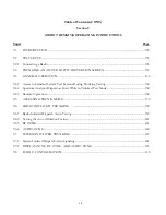
Table of Contents (CONT)
Section 3
OPERATING INSTRUCTIONS (CONT)
Topic
Page
3-7.1.5 SINAD Meter........................................................................................................................43
3-7.1.6 Counter and Decoding Functions ......................................................................................43
3-7.1.7
CABLE FAULT (if equipped) ............................................................................................45
3-7.1.8 GENERAL SEQ DECODE..............................................................................................46
3-7.1.9 Preset Scan (if equipped)......................................................................................................47
3-7.2
Display 49
3-7.2.1 Spectrum Analyzer................................................................................................................49
3-7.2.2 Modulation Scope .................................................................................................................52
3-7.2.3
EXT'L SCOPE......................................................................................................................55
3-7.2.4 SWEEP GENERATE.........................................................................................................55
3-7.2.5
Bar Graphs.............................................................................................................................55
3-7.2.6
Tracking Generator (if equipped).......................................................................................57
3-8
OTHER FUNCTIONS..................................................................................................................................57
3-8.1
Audio Monitor .................................................................................................................................................57
3-8.2
Calibration.........................................................................................................................................................57
3-8.3
Print Function ..................................................................................................................................................57
3-8.4
Special Functions Menu..................................................................................................................................58
3-8.4.1 Special Function Selection ...................................................................................................60
3-8.5
Memory Screens...............................................................................................................................................60
3-8.6
Test Setups (if equipped) ................................................................................................................................62
vi
Summary of Contents for R2600 Series
Page 8: ...3 7 1 3 AC DC Voltmeter 41 3 7 1 4 INT DIST EXT DIST Meter 43 v...
Page 46: ...This Page Intentionally Left Blank xxxvi...
Page 66: ...DISPLAY ZONE RF ZONE AUDIO ZONE Figure 3 1 Screen Zone Arrangement 20...
Page 68: ...Figure 3 2 System Help 22...
Page 83: ...Figure 3 11 General Sequence Mode Select 37...
Page 85: ...39 Figure 3 12 RF Display Zone...
Page 88: ...Figure 3 14 Digital Voltmeter Screens 42...
Page 102: ...Figure 3 22 Bar Graphs 56...
Page 107: ...Figure 3 24 Memory Screens 61...
Page 128: ...This Page Intentionally Left Blank 82...
Page 202: ...This Page Intentionally Left Blank 156...
Page 205: ...Figure 11 1 R 2670 with SECURENET Option Housing 159...
Page 206: ...This Page Intentionally Left Blank 160...
Page 218: ...Figure 13 8 Test Key Programming Display Figure 13 9 External Key Programming Display 172...
Page 225: ...Figure 13 12 Duplex Mode Display Zone 179...
Page 234: ...VOICE Figure 13 17 CLEAR SCOPE Markers 188...
Page 236: ...This Page Intentionally Left Blank 190...
Page 249: ...Figure 14 8 SECURENET CLEAR SCOPE Display of Output Modulation 203...
Page 252: ...This Page Intentionally Left Blank 206...
Page 256: ...210 This Page Intentionally Left Blank...
Page 267: ...Figure 17 7 Encryption Select Display Figure 17 7 Encryption Select Display 221 221...
Page 286: ...This Page Intentionally Left Blank 240...
Page 291: ...Figure 18 1 Radio BER Test Mode Audio Zone Figure 18 2 Radio BER Test Mode BER Meter 245...
Page 293: ...Figure 18 4 Receive BER 247...
Page 298: ...Figure 18 6 ASTRO CLEAR SCOPE Display of Output Modulation 252...
Page 304: ...Figure 21 1 PROJ 25 Version Screen Figure 21 2 PROJ 25 Options Screen 258...
Page 309: ...Figure 21 6 SET UP Display Screen Figure 21 7 Encryption Select Display 263...
Page 335: ...Figure 22 4 PROJ 25 CONV CLEAR SCOPE Display of Output Modulation 289...
Page 339: ...Figure 24 1 PROJ 25 Version Screen Figure 24 2 PROJ 25 Options Screen 293...
Page 354: ...Figure 25 3 Encryption Select Display Figure 25 4 Algorithm Select Display 308...
Page 369: ...B 6 This Page Intentionally Left Blank...
Page 379: ...This Page Intentionally Left Blank F 4...
Page 383: ...This Page Intentionally Left Blank H 2...
Page 389: ...J 4 This Page Intentionally Left Blank...
Page 393: ...This Page Intentionally Left Blank K 4...

