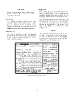
Sensitivity
The SA "Sensitivity: MIN/MAX" field shifts the
baseline reference of the display by 10 db. This is
valid only for 0 db input attenuation. Changing
the input attenuation or changing from ANT to
RF I/O port in the RF Control zone will change
the vertical scale of the Spectrum Analyzer
display. Calibration is maintained between the
display and the signal level present at the input
port so there is no need to compensate for added
attenuation.
Dispersion
Select the band width (20 kHz, 50 kHz, 100 kHz,
200 kHz, 500 kHz, 1 MHz, 2 MHz [optional], 5
MHz [optional], or 10 MHz [optional] per
division) by first moving the cursor to the
dispersion field, then pressing the desired soft-
key. When operating in the optional wider
dispersion settings, it is normal for the response
time of the analyzer to slow down somewhat.
Center frequency is entered from the RF Control
zone and may be conveniently varied with the
TUNING knob.
NOTE
When operating in dispersions greater than
1
MHz/div, the normal monitor metering
functions including "see and hear" audio
monitoring are disabled.
Storage (if equipped)
Optional Storage modes (FREEZE, MAX
HOLD, and PEAK HOLD) are selected by
moving the cursor to the "SA:" field, then
pressing the desired softkey.
Freeze -
Pressing this softkey provides immediate
storage of a spectrum display. This allows cap-
ture of intermittent transmissions etc. for more
detailed analysis. To return to
normal "real time" analysis, simply press the
NORMAL softkey.
Max Hold -
This softkey provides a cumulative storage of
peak levels displayed over time. The time
duration is indefinite subject to reset by
pressing the NORMAL softkey.
The Max-Hold display can be frozen by
switching to the Freeze mode. To re-start the
max-hold operation, re-select the Max-Hold
mode. In any case, this causes the Max-Hold
feature to re-initialize and begin collecting input
samples.
Peak Hold -
This key provides a cumulative storage
capability similar to MAX HOLD. It differs in
that in addition to peak responses, the lower
portions of the display are also shown to permit
observation of "real time" activity.
Average Mode -
Operation in the Average mode continuously
averages the previous 100 spectrum analyzer
measurements and displays the averaged value.
After averaging has been selected, the number
of frames used in the averaging calculation will
be displayed in the "Cnt:" field.
Markers (if equipped)
Select marker operation by moving the cursor to
the "Mrk:" field, then pressing the desired
softkey (OFF, DELTA, or ABS). Selection of
DELTA (
) provides two markers on the SA
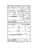
screen (refer to figure 7-19). These permit
relative measurement, between selected points on
the display, of both level and frequency. The
50
Summary of Contents for R2600 Series
Page 8: ...3 7 1 3 AC DC Voltmeter 41 3 7 1 4 INT DIST EXT DIST Meter 43 v...
Page 46: ...This Page Intentionally Left Blank xxxvi...
Page 66: ...DISPLAY ZONE RF ZONE AUDIO ZONE Figure 3 1 Screen Zone Arrangement 20...
Page 68: ...Figure 3 2 System Help 22...
Page 83: ...Figure 3 11 General Sequence Mode Select 37...
Page 85: ...39 Figure 3 12 RF Display Zone...
Page 88: ...Figure 3 14 Digital Voltmeter Screens 42...
Page 102: ...Figure 3 22 Bar Graphs 56...
Page 107: ...Figure 3 24 Memory Screens 61...
Page 128: ...This Page Intentionally Left Blank 82...
Page 202: ...This Page Intentionally Left Blank 156...
Page 205: ...Figure 11 1 R 2670 with SECURENET Option Housing 159...
Page 206: ...This Page Intentionally Left Blank 160...
Page 218: ...Figure 13 8 Test Key Programming Display Figure 13 9 External Key Programming Display 172...
Page 225: ...Figure 13 12 Duplex Mode Display Zone 179...
Page 234: ...VOICE Figure 13 17 CLEAR SCOPE Markers 188...
Page 236: ...This Page Intentionally Left Blank 190...
Page 249: ...Figure 14 8 SECURENET CLEAR SCOPE Display of Output Modulation 203...
Page 252: ...This Page Intentionally Left Blank 206...
Page 256: ...210 This Page Intentionally Left Blank...
Page 267: ...Figure 17 7 Encryption Select Display Figure 17 7 Encryption Select Display 221 221...
Page 286: ...This Page Intentionally Left Blank 240...
Page 291: ...Figure 18 1 Radio BER Test Mode Audio Zone Figure 18 2 Radio BER Test Mode BER Meter 245...
Page 293: ...Figure 18 4 Receive BER 247...
Page 298: ...Figure 18 6 ASTRO CLEAR SCOPE Display of Output Modulation 252...
Page 304: ...Figure 21 1 PROJ 25 Version Screen Figure 21 2 PROJ 25 Options Screen 258...
Page 309: ...Figure 21 6 SET UP Display Screen Figure 21 7 Encryption Select Display 263...
Page 335: ...Figure 22 4 PROJ 25 CONV CLEAR SCOPE Display of Output Modulation 289...
Page 339: ...Figure 24 1 PROJ 25 Version Screen Figure 24 2 PROJ 25 Options Screen 293...
Page 354: ...Figure 25 3 Encryption Select Display Figure 25 4 Algorithm Select Display 308...
Page 369: ...B 6 This Page Intentionally Left Blank...
Page 379: ...This Page Intentionally Left Blank F 4...
Page 383: ...This Page Intentionally Left Blank H 2...
Page 389: ...J 4 This Page Intentionally Left Blank...
Page 393: ...This Page Intentionally Left Blank K 4...


