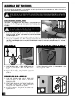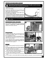
The sanding belt operates at any angle from horizon-
tal to vertical with positive stops at 90° and 45°. These
stops are factory set. However, with use and vibration
over time, they evantually may need minor adjust-
ments.
1.
Make sure that the sander is turned off and un-
plugged.
2.
Place a combination square on the table against
the sanding belt as shown in
A
to verify the 90°
angle of the table.
3.
If needed, loosen the table locking lever
B
, then
adjust the table to 90° to the sanding belt.
4.
Tighten locking lever
B
to lock the table in position
With the table set to 90°, verify and, if needed, adjust
the 90° stop as follows:
1.
Loosen lock nut
C
using a 8 mm wrench.
2.
Adjust set screw
D
using a 2.5 mm allen key until
the screw sits on the stop
E
.
3.
Re-tighten lock nut
C
.
With the table set to 90°, the bevel pointer might need
to be adjusted. Proceed as follows:
Loosen the screw
F
on the pointer mounting bra-
cket and manually align the pointer with the zero on
the bevel scale,
G
, then re-tighten the screw.
ADJUSTING THE 45° BEVEL STOP
Verify the 45° setting by tilting the table down as far as
possible and using a combination square, check the
angle. If needed adjust as for the 90° stop, this time using
the lower stop screw,
H
.
ADJUSTING THE 90° AND 45° BEVEL STOPS - SANDING BELT TABLE
A
B
C
D
E
BEFORE MAKING ANY ADJUSTMENTS, MAKE SURE
THAT THE SWITCH IS IN THE “OFF” POSITION AND
THAT THE POWER CORD IS UNPLUGGED.
F
G
H
1.
Make sure that the sander is turned off and unplugged.
2.
Place a combination square on the table against the sanding disc as shown in
A
to verify the 90° angle of the
table.
Note: The square must not touch the wheel cover, only the sanding disc.
3.
If needed, loosen both lock knobs
B
, then adjust the table to 90° to the sanding disc, then re-tighten both lock
knobs to lock the table in position.
ADJUSTING THE 90° STOP - SANDING DISC TABLE
The sanding disc table can be tilted from 0° to 45° to the front and from 0° to 10° to the rear, with a positive stop at
90°. This stop is factory set. However, with use and vibration over time, it evantually may need minor adjustments.
BEFORE MAKING ANY ADJUSTMENTS, MAKE SURE THAT THE SWITCH IS IN THE “OFF” POSITION AND THAT THE POWER
CORD IS UNPLUGGED.
A
12
B
B
Summary of Contents for 15-035 MI
Page 27: ...Notes 27...


