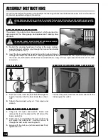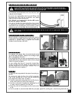
With the table set to 90°, verify and, if needed, adjust the
90° stop as follows:
1.
Loosen lock nut
C
using a 10 mm wrench.
2.
Adjust set screw
D
using the supplied 3 mm allen
key until the screw sits on the table.
3.
Re-tighten lock nut
C
.
INSTALLING/SETTING THE WORKPIECE STOP
The sanding belt table can be used with a fence when operating the sanding belt in the vertical position. When
sanding longer workpieces, with the sanding head in the horizontal position, the table can be replaced with a
workpiece stop as follows.
C
D
BEFORE MAKING ANY ADJUSTMENTS, MAKE SURE THAT THE SWITCH IS IN THE “OFF” POSITION AND THAT THE POWER
CORD IS UNPLUGGED.
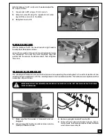
1.
Make sure that the sander is turned off and un-
plugged.
2.
Using a large flat head screwdriver, loosen and re-
move pan head screw
A
.
3.
Remove spring
B
, handle
C
and nut
D
.
4.
Using a 10 mm open end wrench, loosen and re-
move stud
E
, then remove washer
F
and the table
and trunnion assembly
G
.
A
D
B
C
G
E
F
ADJUSTING THE BEVEL POINTER
With the table set to 90°, the bevel pointer might need to
be adjusted. Proceed as follows:
Loosen the screw
E
on the pointer mounting bracket using
the supplied 4 mm allen key, and manually align the
pointer with the zero on the bevel scale,
F
, then re-tighten
the screw.
13
E
F
Summary of Contents for 15-035 MI
Page 27: ...Notes 27...

