background image

113

177

106

109

110

120

108

107

149

148

147

96

67

39

173A

93

69

9

150

71

97

114

111

112

145

146

144

34

74

81

82

47

23

83

84

57

24

74

155

25

154

56

10

54

53

51

52

137

49

48

159

87 88

91

90

164

64

26

86

140

126

89

121

55

125

130

8

58

11

12

78

75

126

100

5

85

3

13

73

46

17

134

14

50

70

76

133

77

22

21

18

79

132

71

80

15

45

43

72

44

20

19

68

16

104

102

7

143

139

156

157

158

31

142

141

174

128

127

161

27

165

118

73

35

80

155

167

154

119

166

138

65

101

66

29

103

63

135

63

30

153

116

28

105

33

151

4

1

152

122

2

60

6

62

59

32

180

179

181

178

175

176

170

73

178

172

73

182

183

184

185

186

115

116

163

162

116

168

169

189

188

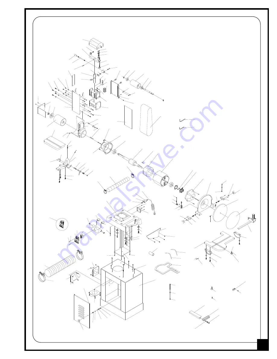
MAIN ASSEMBLY (15-035)

21

Summary of Contents for 15-035 MI

Page 1: ...om being started when key is removed Precision aluminum miter gauge included BELT SIZE 6 X 48 152 X 1220 MM DISC SIZE 12 305 MM BELT SPEED 2250 LIN FPM 686 LIN MPM DISC SPEED 1750 RPM BELT TABLE TILT...

Page 2: ...lace within a period of 24 months from date of purchase any genuine part or parts which upon examination prove to be defective in work manship or material In order to obtain this warranty all defectiv...

Page 3: ...rd 2 year Limited Warranty or under our Limited Lifetime Warranty all defective parts components or machinery must be returned freight or postage prepaid to General International or to a nearby distri...

Page 4: ...iter gauge 11 Center point 11 Adjusting the 90 and 45 bevel stops sanding belt table 12 Adjusting the 90 bevel stop sanding disc table 12 Adjusting the bevel pointer 13 Installing setting the backstop...

Page 5: ...anding belts and all moving parts Use a brush not hands to clear away sanding dust 10 Be sure sanding belts are securely installed on the sanding drums 11 Do not operate the sander if the sanding belt...

Page 6: ...ECTING TO THE POWER SOURCE THIS TOOL IS FOR INDOOR USE ONLY DO NOT EXPOSE TO RAIN OR USE IN WET OR DAMP LOCATIONS CONVERTING THE MOTOR TO 110V Should you need to convert your machine s motor from 220...

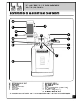
Page 7: ...DUST HOSE F SANDING BELT G BELT GUARD A I B E F G H K C D G J L M N O H MAIN ON OFF SWITCH I BELT SANDER WORK TABLE J MACHINE BASE K STAND L DUST COLLECTOR SWITCH 15 035DC ONLY M BELT TENSION LEVER N...

Page 8: ...R POINT 1 m n o n o p p The sanding belt sanding disc flexible hose and dust collection bag model 15 035DC only are already installed Extra person for help with lifting Phillips head screwdriver Large...

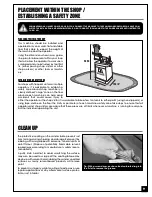
Page 9: ...ensure that all operators and shop visitors are aware that these areas are off limits whenever a machine is running for everyone but the individual operating the unit SERIOUS PERSONAL INJURY COULD OC...

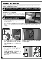
Page 10: ...holes in the base of the sanding head and into the base cabinet C Then open the door and from the inside secure the bolts with four hex nuts and washers using a 14 mm open end wrench and 14 mm sock e...

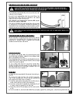
Page 11: ...15 035DC M1 ONLY A B USING THE MITER GAUGE The supplied miter gauge allows for easier and safer sand ing by providing workpiece support when sanding straight 90 or angled ends 0 to 30 The miter gauge...

Page 12: ...ew ADJUSTING THE 45 BEVEL STOP Verify the 45 setting by tilting the table down as far as possible and using a combination square check the angle If needed adjust as for the 90 stop this time using the...

Page 13: ...BEFORE MAKING ANY ADJUSTMENTS MAKE SURE THAT THE SWITCH IS IN THE OFF POSITION AND THAT THE POWER CORD IS UNPLUGGED 1 Make sure that the sander is turned off and un plugged 2 Using a large flat head...

Page 14: ...Place the workpiece stop against the workpiece stop holder and use the washer and bolt to secure in place as shown in N 10 Loosen the locking handle and adjust the po sitionning of the workpiece stop...

Page 15: ...lt disc to reach full speed before sanding To stop the machine Push on the RED STOP panel and wait for the sanding belt disc to come to a complete stop WHEN YOU HAVE FINISHED USING THE MACHINE BE SURE...

Page 16: ...as indicated on the bevel scale B Turn the lock knob clockwise to secure the table in position To tilt the sanding disc table 1 Loosen table locking handles C 2 Tilt the table to the desired angle as...

Page 17: ...USTMENTS WHILE THE MACHINE IS RUNNING ALWAYS TURN OFF AND UNPLUG THE SAN DER BEFORE PERFORMING ANY ADJUSTMENTS KEEP HANDS WELL AWAY FROM THE SANDING BELT AND ALL MOVING PARTS WHEN THE SANDER IS RUNNIN...

Page 18: ...oth bolts on the guard A and remove the upper guard B 3 Loosen and remove both lower guard phillips head screws C and remove the lower guard D 4 Push the belt tension lever E up to release the tension...

Page 19: ...needed clean the bag by lightly tapping it to get rid of any build up of debris 4 Re install the bag or install a new bag and use the bag clamp to hold the bag securely in place EMPTYING CLEANING THE...

Page 20: ...4 225 35 58 4 9 225 9 8 4 6 58 8 44 4 6 58 6 58 68 6 58 35 58 8 2 1 225 8 8 4 85 4 8 OXI OZ XKGQKX 25 2 4 OXI OZ XKGQKX 25 2 4 8 4 2 1 8 2 1 225 8 9 8 4 8 4 225 35 58 4 9 225 9 8 4 6 58 8 44 4 6 58 6...

Page 21: ...130 8 58 11 12 78 75 126 100 5 85 3 13 73 46 17 134 14 50 70 76 133 77 22 21 18 79 132 71 80 15 45 43 72 44 20 19 68 16 104 102 7 143 139 156 157 158 31 142 141 174 128 127 161 27 165 118 73 35 80 155...

Page 22: ...07 106 109 108 110 39 42 41 99 40 98 P U O U T T O O C K P U L L O U T T O L O C K 111 112 113 114 115 116 117 118 119 120 121 122 163 162 68 69 92 123 124 125 85 126 126 127 128 129 131 130 134 133 1...

Page 23: ...BASE BELT PLATE BELT PLATE BRACKET UPPER WHEEL BRACKET BELT COVER UPPER WHEEL BRACKET UPPER WHEEL GUARD UPPER WHEEL SHAFT SHAFT BRACKET QUICK ADJUSTING BEARING UPPER WHEEL ALUM SHAFT BRACKET UPPER WHE...

Page 24: ...REW W WASHER BEARING BALL LOCK KNOB HEX NUT BELT COVER BRACKET PHILLIPS HEAD SCREW W WASHER PHILLIPS HEAD SCREW W WASHER BEARING HEX SCREW FLAT WASHER STOP SCREW ADJUSTING PLATE PHILLIPS HEAD SCREW W...

Page 25: ...ORD FEMALE DOUBLE ROUND PIN DUST HOSE CLIP TERMINAL BLACK TERMINAL WHITE ROUND HEAD PIN INDICATOR FIXED BOLT DUST BAG CLAMP ADJUSTING SPRING SMALL WAVE WASHER BRACKET OF UPPER SHAFT STOP SCREW SWITCH...

Page 26: ...035 187 15036 188 15036 189 DESCRIPTION WASHER SPROCKET WASHER BELT POINTER SCREW FLAT WASHER SWITCH PLATE CLOSED STAND SWITCH ASS Y DUST CHUTE DUST HOSE DUST HOSE CLAMP HEX NUT PHILLIPS HEAD SCREW HE...

Page 27: ...Notes 27...

Page 28: ...umber of the machine and part number Also a brief description of each item and quantity desired 8360 Champ d Eau Montreal Quebec Canada H1P 1Y3 Tel 514 326 1161 Fax 514 326 5565 Parts Service Fax 514...

Reviews: