background image

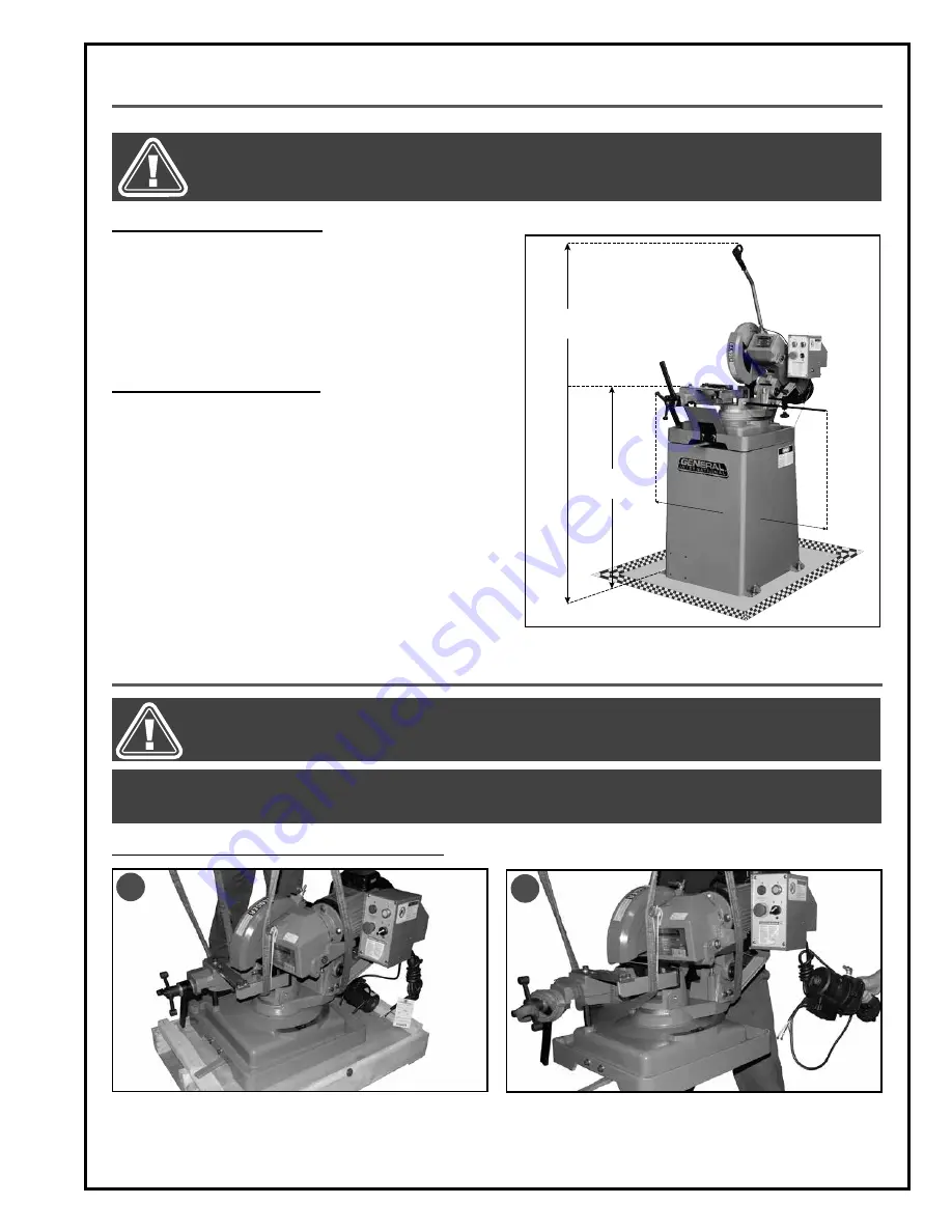
PLACEMENT WITHIN THE SHOP / SAFETY ZONE

THIS COLD CUT SAW MODEL 60-250 IS HEAVY. DO NOT OVER-EXERT. A HOIST OR FORKLIFT WITH STRAPS SHOULD BE 

USED TO LIFT THIS MACHINE. TO LIMIT THE RISK OF SERIOUS INJURY OR DAMAGE TO THE MACHINE, ANY EQUIPMENT 

USED TO LIFT THIS MACHINE SHOULD HAVE A RATED CAPACITY IN EXCESS OF 418 LBS (190 KG).

9

ASSEMBLY INSTRUCTIONS

INSTALLING THE MACHINE HEAD ON THE STAND

TIP: TO ASSEMBLE THIS UNIT, YOU WILL NEED TO LIFT THE HEAD OF THE MACHINE. DUE TO THE WEIGHT OF THE MACHINE, ADEQUATE 

LIFTING EQUIPMENT SUCH AS A JACK, HOIST, OR FORKLIFT WITH STRAPS IS REQUIRED. ANY EQUIPMENT USED TO LIFT THE MA-

CHINE MUST HAVE A MINIMUM WEIGHT CAPACITY OF 418 LBS (190 KG).

BEFORE ASSEMBLING, MAKE SURE THAT THE SWITCH IS IN THE “OFF” POSITION AND THAT THE POWER CORD IS 

UNPLUGGED. DO NOT PLUG IN OR TURN ON THE MACHINE UNTIL YOU HAVE COMPLETED THE ASSEMBLY AND 

INSTALLATION STEPS DESCRIBED IN THIS SECTION OF THE MANUAL.

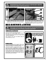
72"

40"

39"

PLACEMENT WITHIN THE SHOP

This machine should be installed and operated only on a 

solid, flat and stable floor that is able to support the weight 

of the machine (418 lbs - 190 kg) and the operator. Using 

the dimensions shown as a guideline, plan for placement 

within your shop that will allow the operator to work unen-

cumbered and unobstructed by foot traffic (either pass-

ing shop visitors or other shop workers) or other tools or 

machinery.

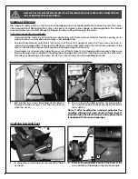
ESTABLISHING A SAFETY ZONE

For shops with frequent visitors or multiple operators, it is 

advisable to establish a safety zone around shop machin-

ery. A clearly defined “no-go” zone on the floor around 

each machine can help avoid accidents that could 

cause injury to either the operator or the shop visitor. 
It is advisable to take a few moments to either paint (using 

non-slip paint) or using tape, define on the floor the limits 

or perimeter of each machines safety zone. Take steps to 

ensure that all operators and shop visitors are aware that 

these areas are off limits whenever a machine is running 

for everyone but the individual operating the unit.

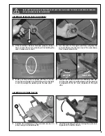
1.

   Remove the bolts holding the machine head to the 

shipping pallet and install appropriate lifting straps 

around the head 

A

Note: Verify the load capacity of the straps.

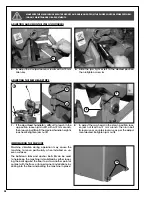
2.

   Lift the machine head using appropriate lifting 

equipment. 

Note: Hold the pump to prevent damage to its power 

cord B.

B

A

Summary of Contents for 60-250

Page 1: ...UT SAW MODEL 60 250 FEATURES 52 rpm blade speed ideal for cutting ferrous materials Mitering capabilities stops at 90 45 left and 45 right Heavy duty design spindle and worm gear box Quick clamp vise for easy workpiece loading Control handle with safety trigger switch Coolant pump system with high volume tank ...

Page 2: ...n confirm from knowledgeable and qualified sources that it is safe to do so Once you ve read through these instructions keep this manual handy for future reference DISCLAIMER The information and specifications in this manual pertain to the unit as it was supplied from the factory at the time of printing Because we are committed to making constant improvements General International reserves the rig...

Page 3: ...ard 2 year Limited Warranty or under our Limited Lifetime Warranty all defective parts components or machinery must be returned freight or postage prepaid to General International or to a nearby distributor repair center or other location designated by General International For further details call our service department at 1 888 949 1161 or your local distributor for assistance when filing your c...

Page 4: ...lling the splash guards 16 Installing the support roller 16 Installing the work stop 17 Basic adjustments and controls 17 20 Connecting to a power source 17 Main On Off switch 17 Magnetic switch 17 Overload protection 18 Adjusting the swivel base 18 19 Adjusting and using the vise 19 20 Adjusting the machine head stops 20 Immobilizing the machine 20 Operating Instructions 21 Checklist before start...

Page 5: ...e rate for which it was designed 14 To minimize risk of injury in the event of workpiece kickback never stand directly in line with the blade or in the potential kickback path of the work piece 15 Avoid working from awkward or off balance posi tions Do not overreach while cutting keep both feet on floor Use out feed support or have an assistant help when cutting long material 16 Keep blade guards ...

Page 6: ...which must also be properly connected to the grounding prong on the plug The outlet must be properly installed and grounded and all electrical connections must be made in accordance with all local codes and regulations CIRCUIT CAPACITY Make sure that the wires in your circuit are capable of handling the amperage draw from your machine as well as any other machines that could be operating on the sa...

Page 7: ... STOP C MOTOR D EMERGENCY STOP BUTTON E COOLANT PUMP ON OFF SWITCH F STOP BUTTON G START BUTTON H DOWNFEED HANDLE I BLADE GUARD J VISE K VISE HANDLE L FLUID RECOVERY TRAY M BASE LOCK LEVER N MITER SCALE O DEPTH STOP P STAND Q QUICK LOCK LEVER C P A H J K F D E G L M N B I Q O ...

Page 8: ...as compared to abrasive wheels on a variety of materials including aluminum steel brass and other work pieces of various sizes and profiles LIST OF CONTENTS QTY A COOLANT TANK 1 B ROLLER STAND 1 C TANK SUPPORT PLATE 1 D WORKPIECE STOP 1 E REAR PANEL 1 F FRONT PANEL 1 G RECOVERY TRAY DRAIN HOSE 1 H HOSE 2 I SPLASH SCREEN 2 J FRONT SHOCK ABSORBER 2 K REAR SHOCK ABSORBER 1 L DOWNFEED HANDLE 1 M FLAT ...

Page 9: ... to support the weight of the machine 418 lbs 190 kg and the operator Using the dimensions shown as a guideline plan for placement within your shop that will allow the operator to work unen cumbered and unobstructed by foot traffic either pass ing shop visitors or other shop workers or other tools or machinery ESTABLISHING A SAFETY ZONE For shops with frequent visitors or multiple operators it is ...

Page 10: ...AL 3 Hold the head above the stand and align the mounting bolts as shown C 4 Place the supplied shock absorbers in the loca tions shown D and lower the head on its stand with the four mounting bolts in the mounting holes on the stand E 5 Secure the head to the stand from below using two 12 mm nuts with two lock washers at the rear F and two 17 mm nuts with two flat washers at the front G INSTALLIN...

Page 11: ... of the coolant hose 6 Fit the end of the hose onto the pump outlet fitting then tighten the hose clamp using a screwdriver Tip Pull on the hose to verify that is fastened securely 2 Align the mounting holes with the corresponding holes on the stand and attach it using two bolts and flat washers B with a 13 mm wrench B A 11 3 Install the pump in the coolant tank opening with the outlet fitting C t...

Page 12: ... Slide the coolant hose onto the fitting on the ma chine head then secure it by using a screwdriver Tip Pull on the hose to verify that is fastened securely 7 Install the pump and the tank on the support plate as shown 8 Align the mounting holes on the second support plate with the corresponding holes on the stand 9 Attach the plate to the stand using four bolts and flat washers with a 13 mm wrenc...

Page 13: ...place of the plug and secure it by tightening two jam nuts B with a wrench C INSTALLING THE DOWNFEED HANDLE A B C BEFORE ASSEMBLING MAKE SURE THAT THE SWITCH IS IN THE OFF POSITION AND THAT THE POWER CORD IS UNPLUGGED DO NOT PLUG IN OR TURN ON THE MACHINE UNTIL YOU HAVE COMPLETED THE ASSEMBLY AND INSTALLATION STEPS DESCRIBED IN THIS SECTION OF THE MANUAL 3 Turn the handle so that the trigger point...

Page 14: ...eral purpose blade 60 255 3 Remove the blade flange screw using a 10 mm Al len wrench Turn clockwise as shown 4 Remove the blade flange from the blade holder 5 Install the blade on the blade holder making sure that the blade is installed with the teeth pointing down as shown B 6 Hold the blade against the blade holder making sure it sits flush then align the two mounting holes C with the correspon...

Page 15: ...OSITION AND THAT THE POWER CORD IS UNPLUGGED DO NOT PLUG IN OR TURN ON THE MACHINE UNTIL YOU HAVE COMPLETED THE ASSEMBLY AND INSTALLATION STEPS DESCRIBED IN THIS SECTION OF THE MANUAL 9 Push on the flange to seat it flush against the blade 10 Tighten the mounting screw counterclockwise to secure the flange and the blade to the holder 11 Lower the blade guard and re install the blade guard arm on i...

Page 16: ...les 2 Slide a splash guard onto the two screws and be hind the flat washers Retighten the two screws then repeat with the other splash guard on the front of the machine 16 INSTALLING THE FRONT PLATE 1 Remove the four screws installed at the bottom front of the stand using a 3 mm Allen key 2 Align the plate mounting holes with the holes in the base then attach it with the four screws BEFORE ASSEMBL...

Page 17: ...r surges power outages or unintentional start up The switch assembly is equipped with a green start button F a red stop button G and a emergency stop button with twist lock out device H Once this button has been pressed the machine can only be started by turn ing the button to the right to release the stop button J The coolant system pump is controlled using switch I To start the pump turn the swi...

Page 18: ... switch on this machine is equipped with an overload protection feature To prevent an elec trical overload from damaging the motor in the event of a spike in line voltage or amperage draw the internal overload protector will automatically be tripped thereby cutting off power to the motor Common causes of such overloads Overworking the motor by forcing the saw particularly with thicker denser mater...

Page 19: ...l the pointer is aligned with the 45 mark Repeat with the right stop LEFT STOP RIGHT STOP ADJUSTING AND USING THE VISE 1 Position the workpiece in the vise and secure it in place using vise handwheel D 2 Lock the workpiece in place turning the quick lock ing lever to the left as shown 3 If the lever does not lock the base properly loosen the screw A with a 6 mm Allen key while holding the lever in...

Page 20: ...rclockwise as per the adjust ment desired Retighten jam nut E C D E B F G IMMOBILIZING THE MACHINE Machine vibration during operation may cause the machine to move particularly when installed on un even surfaces The bolt down tabs and anchor bolts G can be used to help keep the machine immobilized by either lower ing the bolts against the floor to act as another point of contact with the floor or ...

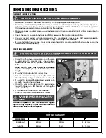
Page 21: ...IN PLACE BEFORE STARTING THE SAW BE SURE THAT THE BLADE IS NOT ALREADY IN CONTACT WITH THE WORKPIECE BURN DANGER DO NOT USE BARE HANDS TO TOUCH THE WORKPIECE AT THE CUT LOCATION UNTIL IT HAS COOLED VERIFY ALL CHECK POINTS BEFORE STARTING FAILURE TO COMPLY CAN RESULT IN SERIOUS INJURIES CHECKLIST BEFORE STARTING 1 Make sure you and any assistants are wearing safe and appropriate workshop attire 2 T...

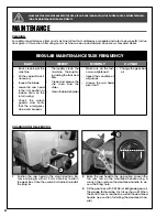
Page 22: ...rks properly Thoroughly clean the machine thoroughly including the tank and filter Clean and grease the vise screw and the slides Clean the blade holder Make sure all the fast ners are tightened Inspect the condition of all guards Grease the saw head pivot shaft Change the gear box oil CHANGING THE GEAR BOX OIL B A C 1 Position the saw head in the down position Re move oil plug A with a 10 mm Alle...

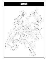
Page 23: ...DIAGRAM 23 ...

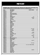
Page 24: ...18 SLIDING VISE 1 60250 A19 WASHER 1 60250 A20 SPRING 1 60250 A21 PLATE 1 60250 A22 CAP SCREW M12 X 25 3 60250 A23 WASHER 5 16 2 60250 A24 CAP SCREW M8 X 20 2 60250 A25 SPRING 1 60250 A26 WASHER 5 16 1 60250 A27 CAP SCREW M8 X 20 1 60250 A28 BLADE GUARD ARM 1 60250 A29 WASHER 1 4 1 60250 A30 CAP SCREW M6 X 12 1 60250 A31 WASHER 1 4 1 60250 A32 NUT M8 1 60250 A33 GUARD ARM BRACKET 1 60250 A34 RETEN...

Page 25: ...2 60250 A75 SHAFT 1 60250 A76 BUSHING 1 60250 A77 CAP SCREW M12 X 55 1 60250 A78 NUT M12 1 60250 A79 LOCK KNOB 1 60250 A80 THREADED SHAFT 1 60250 A81 UPPER ROD 1 60250 A82 LOWER ROD 1 60250 A83 NUT 1 60250 A84 LOCK KNOB 1 60250 A85 RECOVERY FILTER 1 60250 A86 HOOK 3 60250 A87 DRAINAGE 1 60250 A88 WASHER 5 16 2 60250 A89 CAP SCREW M8 X 25 2 60250 A90 CAP SCREW 1 60250 A91 SAW ARM 1 60250 A92 WASHER...

Page 26: ...250 A114 SCREW M5 2 60250 A117 COVER 2 60250 A118 SCREW 2 60250 A119 OIL SEAL 1 60250 A120 GASKET 1 60250 A121 GASKET 1 60250 A122 PLATE BRACKET 1 60250 A123 SPLASH GUARD 1 60250 A124 SPLASH GUARD 1 PARTS LIST BLADE SPECIFICATIONS IMPORTANT When ordering replacement parts always give the model number serial number of the machine and part number Also a brief description of each item and quantity de...

Page 27: ...ANK 1 60250 B08 HOSE 1 60250 B09 HOSE CLAMP 1 60250 B10 WASHER 1 4 4 60250 B11 CAP SCREW M6X16 2 60250 B12 COOLANT PUMP 1 60250 B13 CONNECTING BOLT 1 60250 B14 HOSE CLAMP 1 60250 B15 HOSE 1 60250 B16 HOSE CLAMP 1 60250 B17 VALVE 1 60250 B18 WIRE 1 60250 B21 CAP SCREW M6X15 2 60250 B22 WASHER M8 2 60250 B23 SUPPORT PLATE 1 60250 B24 SCREW M5X6 4 60250 B25 FRONT PLATE 1 60250 B27 NUT 4 60250 B28 SCR...

Page 28: ...WIRING DIAGRAM 28 ...

Page 29: ...NOTES 29 ...

Page 30: ...Follow us 8360 Champ d Eau Montreal Quebec Canada H1P 1Y3 Tel 514 326 1161 Fax 514 326 5565 Parts Service 514 326 5555 Order Desk orderdesk general ca www general ca ...

Reviews: