background image

ENGLISH

8

NOTE: 

DO NOT over tighten Air Regulator or Air Chuck.

INSTALLING THE AIR FILTER 

The metal Air Filter is installed into the threaded port of the cylinder head.
1.  Thread the Air Filter into the Cylinder Head by turning the Air Filter 

clockwise.

2.  Securely tighten the Air Filter in place with a wrench.

NOTE: 

DO NOT over tighten Air Filter.


OPERATION 

BEFORE OPERATING YOUR NEW AIR COMPRESSOR 

Please check the following points carefully:


1.  Check that all nuts and bolts are secure.
2.  Make sure oil has been properly added to compressor. (See Installing 

Oil and Oil Breather Cap section.)

INITIAL START-UP PROCEDURE

1.  Open the Air Tank Drain Valve to permit air to escape, preventing air 

pressure buildup in the air tank.

2.  Run the compressor for a minimum of 20 minutes in this “no-load” 

position to lubricate the piston and bearings.

3.  Close Air Tank Drain Valve. Your compressor is ready for use.

Depending on the CFM draw of the tools being operated, your new Air 

Compressor can be used for operating paint sprayers, air tools, grease 

guns, airbrushes, caulking guns, abrasive blasters, tire & plastic toy 

inflation, spraying weed killer and insecticides, etc. Proper adjustment of 

the Air Pressure Regulator is necessary for all of these operations. Refer 

to the air pressure specifications provided with the tool you are using.

GENERAL OVERVIEW

To compress air, the piston moves up and down in the cylinder. On the 

down stroke air is drawn in through the valve inlet. The discharge valve 

remains closed. On the upstroke of the piston air is compressed. The inlet 

valve closes and air is forced out through the discharge valve, through 

the check valve, and into the air tank. Working air is not available until 

the compressor has raised the tank pressure above that required at the 

air service connection. The air inlet filter openings must be kept clear of 

obstructions, which could reduce air delivery of the compressor.

INSTALLATION AND LOCATION

Locate the compressor in a clean, dry and well ventilated area. The 

compressor should be located 12 to 18 inches from walls or any other 

obstruction which would interfere with airflow. Compressor should be 

located in a temperature controlled area between 32° and 95° fahrenheit. 

Place the compressor on a firm, level surface. The compressor is designed 

with heat dissipation fins which allow for proper cooling. Keep the fins (and 

all other parts which collect dust or dirt) clean. A clean compressor runs 

cooler and provides longer service. Do not place rags, containers or other  

material on top of the compressor.

CONNECTING TO POWER SOURCE

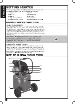
This air compressor is designed to operate on a properly grounded 120 

volt, 60Hz, single phase, alternating current (ac) power source with a 

fused 20 amp time delayed fuse or circuit breaker. It is recommended that 

a qualified electrician verify the ACTUAL VOLTAGE at the receptacle into 

which the unit will be plugged and confirm that the receptacle is properly 

fused and grounded. The use of the proper circuit size can eliminate 

nuisance circuit breaker tripping while operating your air compressor.

!

Summary of Contents for AC1104

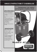
Page 1: ...quiet operation Pull behind two wheel design Includes air line regulator two easy to read pressure gauges allows setting exact line pressure Quick connect fitting Tough powder coated tank finish SPECIFICATIONS Motor 120V 60Hz Power 1500W Max pressure 115psi No load speed 3400 rpm Air delivery 3 8cfm 40psi 2 4cfm 90psi Tank size 10 5 gal 46 25 L Net weight 61 7 lb 28 kg ...

Page 2: ... are committed to making constant improvements General International reserves the right to make changes to components parts or features of this unit as deemed necessary without prior notice and without obligation to install any such changes on previously delivered units Reasonable care is taken at the factory to ensure that the specifications and information in this manual corresponds with that of...

Page 3: ...ce THE WARNINGS CAUTIONS AND INSTRUCTIONS discussed in this instruction manual cannot cover all possible conditions or situations that could occur It must be understood by the operator that common sense and caution are factors which cannot be built into this product but must be supplied by the operator IMPORTANT SAFETY INSTRUCTIONS The purpose of safety symbols is to attract your attention to poss...

Page 4: ...YOUR TOOL Read this manual carefully Learn the tool s applications and limitations as well as specific potential hazards peculiar to it 9 REMOVE ADJUSTING KEYS OR WRENCHES BEFORE TURNING THE TOOL ON A wrench or key that is left attached to a moving part of the tool may result in personal injury 10 KEEP WORK AREA CLEAN AND WELL LIT Cluttered or dark work areas invite accidents 11 KEEP CHILDREN AWAY...

Page 5: ...ITH ALL WARNING LABELS ON UNIT 25 DRAIN TANK OF MOISTURE AFTER EACH USE If compressor is not to be used for extended periods of time leave tank drain valve open to allow moisture to completely drain from tank 26 DO NOT TAMPER WITH SAFETY VALVE THE SAFETY VALVE IS FACTORY SET FOR YOUR MODEL AIR COMPRESSOR ANY USER ADJUSTMENTS TO SAFETY VALVE WILL AUTOMATICALLY VOID WARRANTY 27 AIR COMPRESSORS GET H...

Page 6: ...tacle is properly grounded The use of the proper circuit size can eliminate nuisance circuit breaker tripping when using your tool CAUTION DO NOT OPERATE THIS TOOL if the ACTUAL power source voltage is less than 105 volts AC or greater than 132 volts AC Contact a qualified technician if this problem exists Improper performance and or damage to the tool will result if operated on inadequate or exce...

Page 7: ...ed to the air chuck I SAFETY VALVE The Safety Valve device relieves pressure from the Air Tank in the event of excessive pressure build up Safety Valve is preset at factory Do not attempt to make any adjustments to the Safety Valve Periodically pull ring on the Safety Valve end to check that it is working properly J AIR TANK Powder coated steel tank with a 9 gallon capacity stores the compressed a...

Page 8: ... through the valve inlet The discharge valve remains closed On the upstroke of the piston air is compressed The inlet valve closes and air is forced out through the discharge valve through the check valve and into the air tank Working air is not available until the compressor has raised the tank pressure above that required at the air service connection The air inlet filter openings must be kept c...

Page 9: ...l an air hose equipped with a 1 4 male coupler 1 Pull back on Air Chuck outer sleeve to allow coupler to be fully inserted into Air Chuck 2 Insert coupler into Air Chuck 3 Release outer sleeve of Air Chuck 4 Verify that air hose is securely connected to Air Chuck by pulling on air hose ADJUSTING THE AIR PRESSURE Your Air Compressor is supplied with an Air Pressure Regulator This Regulator adjusts ...

Page 10: ...THE COMPRESSOR OIL NOTE This compressor uses only SAE 5W 30 motor oil Oil will begin to drain as Oil Sight Glass is loosened Place a funnel and oil pan in place BEFORE loosening Oil Sight Glass 1 Remove the Oil Sight Glass by turning counter clockwise with wrench 2 Once Oil Sight Glass is removed tilt Air Compressor backwards to allow all of the oil to drain out of the crankcase 3 Once oil is drai...

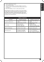
Page 11: ...s are susceptible to damage from the various types of commercial solvents TROUBLESHOOTING TROUBLE POSSIBLE CAUSE CORRECTIVE ACTION Compressor Will Not Start 1 Blown fuse or circuit breaker tripped 2 Loose electrical connections 1 Replace or reset fuse circuit breaker 2 Check wiring connections Low Pressure 1 Restricted air filter 2 Defective check valve 3 Air leak in safety valve 1 Replace air fil...

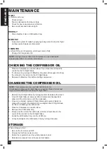
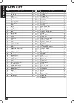
Page 12: ...t 1 34 Spring washer 4 35 Screw 4 36 Lock washers 1 37 Piston 1 38 Gudgeon pin 1 ITEM Description QTY 39 Cylinder gasket 1 40 Cylinder 1 41 Oil clean ring 1 42 Valve plate assy 1 43 Valve plate 1 44 Limit pin 2 45 Cylinder cover 1 46 Air filter 1 47 Exhaust pipe assy 1 48 Non return valve 1 49 Unloader pipe 1 50 Rubber handle sheath 1 51 Screw 4 52 Spring washer 4 53 Flat washer 4 54 Back motor mo...

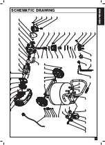
Page 13: ...ENGLISH 13 141205 SCHEMATIC DRAWING ...

Page 14: ...ENGLISH 14 ...

Page 15: ...ception de roues tractées deux Comprend régulateur de ligne d air deux jauges de pression facile à lire permet la définition exacte de pressurisation Raccord rapide Réservoir enduit poudre dur terminer SPÉCIFICATIONS Moteur 120V 60Hz Puissance 1500W Pression maximale 115psi Vitesse sans charge 3400 rpm Livraison de pression d air 3 8 pi min à 40 lb po 2 4 pi min à 90 lb po Capacité du réservoir 10...

Page 16: ...le consentement écrit de General International annuleront la garantie CLAUSE DE NON RESPONSABILITÉ L information et les caractéristiques présentées dans ce manuel se rapportent à la machine telle qu elle est sortie de l usine au moment de mettre sous presse En raison de son souci d amélioration constante General International se réserve le droit de modifier des composantes des pièces ou des caract...

Page 17: ...ts de sécurité les précautions l assemblage le fonctionnement les procédures d entretien la liste des pièces et les schémas des pièces Gardez votre facture avec ces instructions Écrivez votre numéro de facture à l intérieur de la page couverture Gardez les instructions ainsi que la facture dans un endroit sûr et sec pour référence future LES AVERTISSEMENTS LES PRÉCAUTIONS ET LES instructions discu...

Page 18: ...les dans un endroit restreint L endroit pulvérisé doit être ventilé Ne pas fumer lors de la pulvérisation et ne pas pulvériser où il y ait des flammes ou des étincelles Garder les compresseurs aussi loin que possible de l endroit pulvérisé ATTENTION 1 APPRENEZ À CONNAÎTRE VOTRE OUTIL Lisez ce manuel attentivement Apprenez les usages ainsi que les limitations de l outil et les dangers potentiels sp...

Page 19: ...ESSION NOMINALE DE TOUT COMPOSANT DU SYSTÈME 15 PROTÉGEZ LES MATÉRIAUX ET LES CONDUITES D AIR CONTRE LES DOMMAGES ET LES PERFORATIONS Gardez le tuyau et le câble d alimentation éloignés des objets tranchants des endroits humides des produits chimiques de l huile etc 16 VÉRIFIEZ L ÉTAT DES TUYAUX avant chaque usage N utilisez pas un tuyau endommagé Si le tuyau est endommagé remplacez le immédiateme...

Page 20: ... qualifié vérifie le VOLTAGE RÉEL à la prise de courant dans laquelle l outil sera branché afin de confirmer aussi si la mise à la terre est correctement effectuée L utilisation d un circuit de taille approprié peut éliminer le déclenchement du disjoncteur lorsque vous utilisez votre outil ATTENTION NE FAITES PAS FONCTIONNER CET OUTIL si le voltage de la source d alimentation RÉELLE est inférieur ...

Page 21: ...ès lentement pour éviter d endommager l équipement et pour empêcher les blessures E FILTRE À AIR Ce filtre en métal résistant assure le fonctionnement propre de votre compresseur en filtrant les impuretés F BOUCHON DU RENIFLARD D HUILE Lors du fonctionnement du moteur du compresseur de l air pressurisé doit être dégagé du carter Le bouchon du reniflard d huile permet l évacuation de l air accumulé...

Page 22: ... Retirez le bouchon d expédition du trou de remplissage d huile situé sur la surface supérieure du couvercle de carter à l arrière du compresseur d air 3 Versez lentement de l huile dans le trou de remplissage jusqu à ce que le niveau d huile soit au centre du point rouge marqué sur le voyant de niveau d huile Remarque N utilisez que de l huile à moteur SAE 5W 30 dans ce compresseur 4 Insérez le b...

Page 23: ...e et l air est forcé à travers la soupape de décharge et la soupape de retenue pour entrer ensuite dans le réservoir d air L air du réservoir n est pas disponible pour l utilisation avant que la pression dans le réservoir n ait dépassée la pression d air requise à la connexion de service Les ouvertures du filtre à l entrée d air doivent être propres et sans obstructions qui pourraient réduire le d...

Page 24: ...mandrin pneumatique vers l arrière pour permettre d insérer le raccord entièrement dans le mandrin pneumatique 2 Insérez le raccord dans le mandrin pneumatique 3 Relâchez le manchon externe du mandrin pneumatique 4 Vérifiez que le tuyau d air est bien connecté au mandrin pneumatique en tirant sur le tuyau d air RÉGLAGE DE LA PRESSION D AIR Votre compresseur d air est doté d un régulateur de pressi...

Page 25: ... huile 3 Remettez en place le bouchon du reniflard d huile avant de mettre le compresseur en marche CHANGEMENT DE L HUILE DU COMPRESSEUR D AIR REMARQUE N utilisez que de l huile à moteur SAE 5W 30 dans ce compresseur L huile commencera à sortir à mesure que le voyant de niveau d huile est desserré Placez un entonnoir et un récipient à huile sous l ouverture AVANT de desserrer le voyant de niveau d...

Page 26: ... endommagé et sans fissures fils dénudés etc Évitez d utiliser des solvants pour nettoyer les pièces en plastique La plupart des plastiques sont susceptibles à être endommagés par les divers types de solvants commerciaux DÉPANNAGE PROBLÈME CAUSE POSSIBLE CORRECTION Le compresseur ne se mat pas en marche 1 Fusible grillé ou disjoncteur déclenché 2 Connexions électriques desserrées 1 Remplacez le fu...

Page 27: ... ressort 4 35 Vis 4 36 Rondelle de sécurité 1 37 Piston 1 38 Axe de piston 1 LISTE DE PIÈCES PIÈCE DESCRIPTION QTÉ 39 Joint statique 1 40 Cylindre 1 41 Segment racleur 1 42 Ens Plat de soupape 1 43 Plat de soupape 1 44 Goupille d arrêt 2 45 Culasse 1 46 Filtre à air 1 47 Ens Tuyau d échappement 1 48 Clapet de non retour 1 49 Tuyau réducteur de puissance 1 50 Manchon en caoutchouc 1 51 Vis 4 52 Ron...

Page 28: ...FRANÇAIS 28 SCHÉMA ...

Reviews: