background image

ENGLISH

10

Monthly

1.  Inspect air system for leaks by applying soapy water to all joints. Tight-

en these joints if leaks are discovered.

6 Months

 (or after 250 hours of operation - whichever comes first)

1.  Change Air Compressor Oil.

NOTE: 

Change oil more often if Air Compressor is used near paint 

spraying operations or in dusty environments.

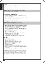
Checking the Air Compressor Oil

1.  Place Air Compressor on level surface. The oil level should be at the 

red dot on the Oil Sight Glass.

2.  If oil level is low, remove Oil Breather Cap and add enough oil to bring 

the oil level to the red dot on the Oil Sight Glass.

3.  Replace Oil Breather Cap before starting compressor.

Changing the Air Compressor Oil

NOTE: 

This compressor uses only SAE 5W-30 motor oil. 

Oil will begin to drain as Oil Sight Glass is loosened. Place a funnel and 

oil pan in place BEFORE loosening Oil Sight Glass.

1.  Remove the Oil Sight Glass by turning counter clockwise with wrench.
2.  Once Oil Sight Glass is removed, tilt Air Compressor backwards to 

allow all of the oil to drain out of the crankcase.

3.  Once oil is drained, replace Oil Sight Glass and securely tighten in 

place with a wrench. Be careful not to overtighten the Oil Sight Glass, 

as this could damage the rubber seal.

4.  Place Air Compressor on level surface.
5.  Remove the Oil Breather Cap.
6.  Slowly pour the oil into the oil fill hole, until the oil level rises to the 

center of the red dot on the Oil Sight Glass.

7.  Install the Oil Breather Cap into the oil fill hole.
8.  Firmly hand tighten the Oil Breather Cap by turning clockwise.

STORAGE

When storing your tool:
1.  Be sure the tool is turned OFF.
2.  Unplug the tool from power source.
3.  Rotate the regulator to set the outlet pressure to zero.
4.  Release air pressure from all hoses and air tank(s).
5.  Drain all moisture from air tank(s).
6.  Fully close drain valve(s).
7.  Protect electrical cord and air hoses from damage (such as being 

stepped on or driven over). Wrap all cords and hoses loosely around 

air compressor.

8.  Place air compressor in a cool, dry, safe, and indoor location. 

Always inspect the tool before use, and make sure it is in good working 

condition. Make sure all air vents are clear, (use compressed air to clean 

the machine where possible). Check the power cable to make sure it is 

intact and free from cracks, bare wires etc. Avoid using solvents when 

cleaning plastic parts, most plastics are susceptible to damage from the 

various types of commercial solvents.

Summary of Contents for AC1106

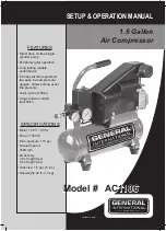
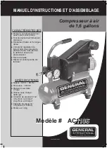
Page 1: ...ng lasting reliable performance Includes air line regulator two easy to read pressure gauges allows setting exact line pressure Quick connect fitting Tough powder coated tank finish SPECIFICATIONS Mot...

Page 2: ...are committed to making constant improvements General International reserves the right to make changes to components parts or features of this unit as deemed necessary without prior notice and without...

Page 3: ...e THE WARNINGS CAUTIONS AND INSTRUCTIONS discussed in this instruction manual cannot cover all possible conditions or situations that could occur It must be understood by the operator that common sens...

Page 4: ...rn the tool s applications and limitations as well as specific potential hazards peculiar to it 2 REMOVE ADJUSTING KEYS OR WRENCHES BEFORE TURNING THE TOOL ON A wrench or key that is left attached to...

Page 5: ...K OF MOISTURE AFTER EACH USE If Compressor is not to be used for extended periods of time leave tank drain valve open to allow moisture to completely drain from tank 19 DO NOT TAMPER WITH SAFETY VALVE...

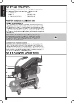
Page 6: ...f the proper circuit size can eliminate nuisance circuit breaker tripping when using your tool CAUTION DO NOT OPERATE THIS TOOL if the ACTUAL power source voltage is less than 105 volts AC or greater...

Page 7: ...the air chuck I SAFETY VALVE not shown The Safety Valve device relieves pressure from the Air Tank in the event of excessive pressure build up Safety Valve is preset at factory Do not attempt to make...

Page 8: ...through the valve inlet The discharge valve remains closed On the upstroke of the piston air is compressed The inlet valve closes and air is forced out through the discharge valve through the check va...

Page 9: ...inserted into Air Chuck 2 Insert coupler into Air Chuck 3 Release outer sleeve of Air Chuck 4 Verify that air hose is securely connected to Air Chuck by pulling on air hose ADJUSTING THE AIR PRESSURE...

Page 10: ...tighten in place with a wrench Be careful not to overtighten the Oil Sight Glass as this could damage the rubber seal 4 Place Air Compressor on level surface 5 Remove the Oil Breather Cap 6 Slowly pou...

Page 11: ...1 10 Rotor 1 11 Bearing 1 12 Seal ring 1 13 Crankcase 1 14 Oil baffle plate 1 15 Crankcase cover 1 16 Oil sight glass assembly 1 17 Screw 4 18 Breather assembly 1 19 Capacitor 2 20 Lock washer 2 21 N...

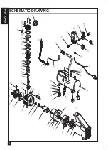
Page 12: ...ENGLISH 12 SCHEMATIC DRAWING...

Page 13: ......

Page 14: ......

Page 15: ...eux Rendement fiable et de longue dur e Comprend r gulateur de ligne d air deux jauges de pression facile lire permet la d finition exacte de pressurisation Raccord rapide R servoir enduit poudre dur...

Page 16: ...le consentement crit de General International annuleront la garantie CLAUSE DE NON RESPONSABILIT L information et les caract ristiques pr sent es dans ce manuel se rapportent la machine telle qu elle...

Page 17: ...ements de s curit les pr cautions l assemblage le fonctionnement les proc dures d entretien la liste des pi ces et les sch mas des pi ces Gardez votre facture avec ces instructions crivez votre num ro...

Page 18: ...e pas pulv riser avec des liquides inflammables dans un endroit restreint L endroit pulv ris doit tre ventil Ne pas fumer lors de la pulv risation et ne pas pulv riser o il y ait des flammes ou des ti...

Page 19: ...ls bien entretenus avec des ar tes de coupe ac r es sont moins passibles de se coincer dans la pi ce de travail et sont plus faciles ma triser 14 NE D PASSEZ JAMAIS LA PRESSION NOMINALE DE TOUT COMPOS...

Page 20: ...CA prot g par un disjoncteur de 15 A coupure diff r e Il est recommand qu un lectricien qualifi v rifie le VOLTAGE R EL la prise de courant dans laquelle l outil sera branch afin de confirmer aussi si...

Page 21: ...ntement pour viter d endommager l quipement et pour emp cher les blessures E FILTRE air Ce filtre en m tal r sistant assure le fonctionnement propre de votre compresseur en filtrant les impuret s F BO...

Page 22: ...e niveau 2 Retirez le bouchon d exp dition du trou de remplissage d huile situ sur la surface sup rieure du couvercle de carter l arri re du compresseur d air 3 Versez lentement de l huile dans le tro...

Page 23: ...e se ferme et l air est forc travers la soupape de d charge et la soupape de retenue pour entrer ensuite dans le r servoir d air L air du r servoir n est pas disponible pour l utilisation avant que la...

Page 24: ...e 3 Rel chez le manchon externe du mandrin pneumatique 4 V rifiez que le tuyau d air est bien connect au mandrin pneumatique en tirant sur le tuyau d air R GLAGE DE LA PRESSION D AIR Votre compresseur...

Page 25: ...l 2 Une fois que le voyant de niveau d huile est retire inclinez le compresseur d air vers l arri re pour permettre l huile de vidanger du carter 3 Une fois que toute l huile est vidang e remettez en...

Page 26: ...ncteur d clench 2 Connexions lectriques desserr es 1 Remplacez le fusible ou r initialisez le disjoncteur 2 Inspectez les connexions lectriques Basse pression 1 Filtre air obstru 2 Soupape de retenue...

Page 27: ...dre 1 32 Joint statique pour plat de soupape 1 33 Plat de soupape 2 34 Joint garniture 1 35 Garniture de vanne 2 NO DE REF DESCRIPTION QT 36 Joint statique pour carter 1 37 Coude 90 1 38 Calotte de cy...

Page 28: ...FRAN AIS 28 SCH MA...
Reviews: