Models FL3100/3101
5
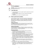
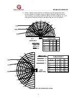
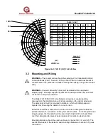
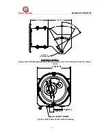
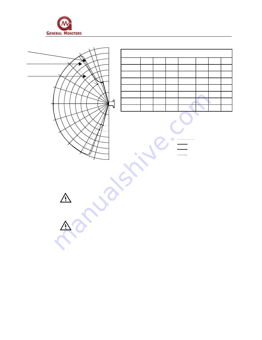
Figure 3A-3 FL3101 (UV) Field of View
3.3
Mounting and Wiring
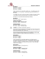
WARNING - The conduit entries should be sealed per the Canadian Electrical
Code Handbook (Part 1, Section 18-154) or NEC 500-3d. Additional benefit of
conduit seals is the prevention of water entering the housing through the conduit
entry.
WARNING - Unused cable entry holes must be sealed with an approved
stopping plug. Red caps supplied by GM are for dust protection only and must
not be left on unit when installed.
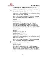
The Model FL3100/FL3101 Flame Detector should be mounted pointing
downward so that dust/moisture will not accumulate on the optical window(s).
The detector(s) should be mounted in locations, which will inhibit people or
objects from obscuring the detector’s cone of vision.
Detectors should be mounted such that the conduit or cable gland entries are
pointed downward. See above warning for conduit entries. For cable glands and
stopping plugs, the threads should be sealed with Castrol EP and boots fitted
over the cable gland to prevent water ingress at the cable-to-gland junction.
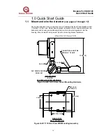
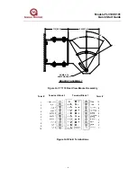
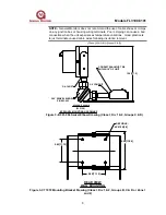
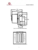
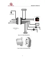
Mounting hardware should be used as shown in Figures 3-B, 3-C and 3-D. The
overall dimensions of the detector and mounting hardware are shown in Figures
3-E and 3-F.
0°
VERTICAL
50'
75%
50'
50'
50'
50'
<20'
<20'
-45°
-60°
-70°
-30°
-15°
50'
-75°
100%
75%
50%
- 70°
- 75°
- 45°
- 60°
25'
<20'
50'
VERTICAL
- 15°
- 30°
0°
50'
50'
50'
100%
50'
50'
50'
50'
<20'
<20'
50'
+ 70°
+ 75°
+ 60°
+ 45°
<20'
20'
<20'
<20'
50'
30'
<20'
<20'
20'
50'
50'
50'
50%
+ 30°
+ 15°
VERTICAL
0°
TABLE CHART
50'
50'
50'
50'
50'
100%
50'
75%
50'
50'
50%
50'
20'
50'
+15°
35'
40'
45'
25'
30'
+30°
+45°
15'
10'
+60°
+70°
+75°
(±5°)
SENSITIVITY
50%
100%
75%


