Models FL3100/3101
11
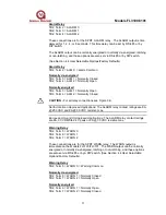
Alarm Relay
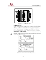
TB2, Term 2 = ALARM C
TB2, Term 3 = ALARM 1
TB2, Term 4 = ALARM 2
These connections are for the SPDT ALARM relay. The ALARM output is time
delayed for 1, 2, 4, or 8 seconds. This time delay can be set by RS-485 or by
DIP switch.
The ALARM output can be normally energized or normally de-energized, latching
or non-latching, and these options are also set via RS-485 or by DIP switch.
(See Section 4.4 User Selectable Options/Factory Defaults)
Alarm Relay
TB2, Term 2 = ALM C = Alarm Common
Normally de-energized
TB2, Term 3 = ALM 1 = Normally Closed
TB2, Term 4 = ALM 2 = Normally Open
Normally energized
TB2, Term 3 = ALM 1 = Normally Open
TB2, Term 4 = ALM 2 = Normally Closed
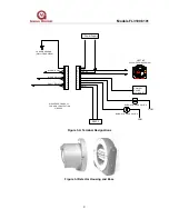
CAUTION - For all relay connections see Figure 3-K.
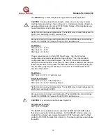
North American Approved Applications: The ALARM relay contact ratings are 8A
@ 250 VAC and 8A @ 30 VDC resistive max.
European Union (EU) Approved Applications: The ALARM relay contact ratings
are 8A, 30 V RMS/42.4 V peak or 8A @ 30 VDC resistive max.
Warning Relay
TB2, Term 5 = WARN C
TB2, Term 6 = WARN 1
TB2, Term 7 = WARN 2
These connections are for the SPDT WARN relay. The WARN output is
immediate on the Models FL3100/FL3101. The WARN output can be normally
energized or normally de-energized, latching or non-latching, and these options
are also set via RS-485 or by a DIP switch. (See Section 4.4 User Selectable
Options/Factory Defaults).
Warning Relay
TB2, Term 5 = WARN C = Warning Common
Normally de-energized
TB2, Term 6 = WARN 1 = Normally Closed
TB2, Term 7 = WARN 2 = Normally Open
Normally energized
TB2, Term 6 = WARN 1 = Normally Open
TB2, Term 7 = WARN 2 = Normally Closed

