Models FL3100/3101
12
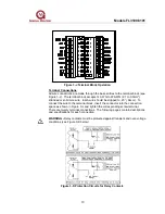
The WARN relay contact ratings are 8A @ 250VAC and 8A @ 24VDC.
CAUTION - Inductive loads (bells, buzzers, relays, etc.) on dry relay contacts
must be clamped down as shown in Figure 2-J. Unclamped inductive loads can
generate voltage spikes in excess of 1000 Volts. Spikes of this magnitude may
cause false alarms and contact damage.
North American Approved Applications: The ALARM relay contact ratings are 8A
@ 250 VAC and 8A @ 30 VDC resistive max.
European Union (EU) Approved Applications: The ALARM relay contact ratings
are 8A, 30 V RMS/42.4 V peak or 8A @ 30 VDC resistive max.
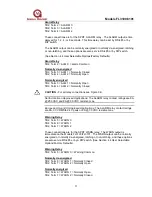
Fault Relay
TB2, Term 8 = FLT C
TB2, Term 9 = FLT 1
TB2, Term 10 = FLT 2
These connections are for the SPDT FAULT relay. The FAULT output
configuration is normally energized and non-latching. This is the standard
configuration and it cannot be changed. The FAULT circuit will be activated
during the time-out function, a low power or loss of power condition, and during a
failed COPM check. During these conditions the FAULT relays will de-energize
and the analog output signal will drop to 0mA (2mA for COPM Faults) for the
duration of the FAULT.
Fault Relay
TB2, Term 8 = FLT C = Fault Common
Normally energized
TB2, Term 9 = FLT 1 = Normally Open
TB2, Term 10 = FLT 2 = Normally Closed
North American Approved Applications: The ALARM relay contact ratings are 8A
@ 250 VAC and 8A @ 30 VDC.
European Union (EU) Approved Applications: The ALARM relay contact ratings
are 8A, 30 V RMS/42.4 V peak or 8A @ 30 VDC resistive max.
CAUTION - For all relay connections see Figure 3-K.
Alarm Reset Terminal
TB1, Term 3 = RESET
The RESET, when activated, returns a latched ALARM and/or WARN output,
that is no longer valid, to its original state. For this RESET function, place one
contact of a normally open momentary switch to TB1 Terminal 3 and the other
contact to DC COM (the detector’s common). To activate, just press and release
the switch.

