Models FL3100/3101
14
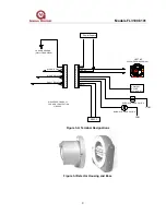
These are the power connections. The supply voltage range is 20 to 36VDC at
the detector (low voltage is detected at approximately 18.5 VDC). The following
maximum cable lengths apply for a +24VDC supply (maximum 20-ohm loop):
Cable
AWG
Run
Feet
Cable
mm
2
Run
Meters
14
1370
2.5
4500
16
715
1.5
2340
18
470
1.00
1540
20
300
0.75
970
22
205
0.50
670
MODBUS Interface
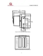
TB1, Term 1 = DATA+
TB1, Term 2 = DATA-
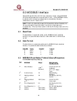
These are the connections for the MODBUS interface. It is used to either query
the unit’s status or to configure the unit. See Section 8, for detailed information
on MODBUS RTU Protocol.
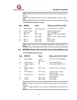
NOTE - If Dual MODBUS output is ordered, then the 0-20mA output is not
available and the wiring terminals for the second MODBUS channels are:
TB1, Term 5 = DATA2+
TB1, Term 6 = DATA2-
Chassis Ground
TB2, Term 1 = CHAS GND
This connection is available for use in wiring that requires a connection to
chassis ground.
Connection to Fire Cards/Panels
For special applications where the detectors are to be wired together for
monitoring via standard fire cards, GM will factory-fit EOL and alarm resistors. If
this special option is required, please specify at time of order and provide the
following information:
•
Specify one or two resistors (i.e. Alarm only, or alarm resistor and EOL).
•
Specify value of resistors.
Where detectors are used in conjunction with a GM Model IN042 card, values
would be 470 ohm Alarm resistor and 5.6K EOL. The EOL resistors are onboard
the IN042, selectable by DIP-switches.
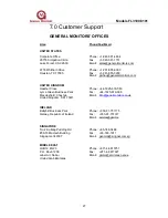
Contact General Monitors or an authorized representative for further details.
European Union (EU) Approved Applications: Interconnecting cables must have
an overall screen or screen and armor. Cables BS5308 Part 2, Type 2, or
equivalent are suitable. Note that the terms ‘screen’ and ‘shield’ are equivalent
for the purpose of this manual. The cable armor must be terminated in a suitable
cable gland at the detector to ensure a positive electrical connection.


