Models FL3100/3101
16
4.0 Operation
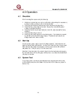
4.1 Checklist
Prior to starting the system verify the following:
1.
Inhibit any external devices, such as automatic extinguishing fire suppression
systems or others, which you do not want activated.
2.
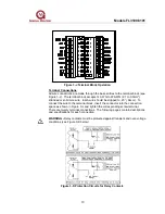
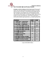
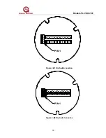
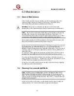
Verify that the DIP-switch settings are set for the desired configuration.
3.
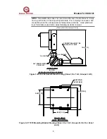
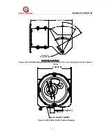
Verify that the unit is properly mounted. Ensure the conduit/cable gland
entries are pointed downward.
4.
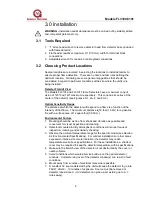
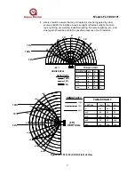
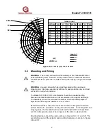
Verify the field of view for each detector covers the area intended for flame
detection.
5.
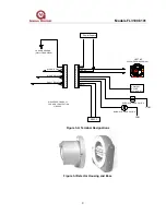
Verify that the wiring is correct.
6.
Verify that the power supply is connected properly. The detector is powered
by +24VDC (20 to 36 VDC voltage range). The detector will output a low
voltage fault at 18.5 VDC or below.
4.2
Start Up
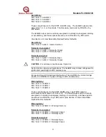
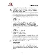
To start up the system, apply power to the flame detectors. Each detector will
begin its self-test start up sequence. For the first 10 seconds, the unit will output
0mA, the fault relay stays de-energized, and the green and red LED will flash
alternately for 1.0 second, each, or .05 seconds, each.
After this 10 second period, the unit will output 4mA, the fault relay will energize,
the red LED will turn off, and the green LED will turn on constant and briefly flash
off every 10 seconds.
4.3 System
Test
To test the system, use the General Monitors Test Lamp Model TL103 for the
FL3100 Flame Detector or the Model TL100 for the FL3101 Detector. (Refer to
Section 5.3).

