Models FL3100/3101
17
4.4
User Selectable Options/Factory Defaults
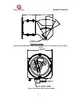
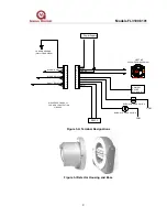
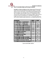
All settings on the Models FL3100 and FL3101 are done via a DIP switch on the
Power/Relay Board or via MODBUS (overrides switch settings). To set these
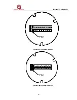
options, remove the detector head from the Base Assembly and locate the DIP
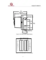
switch (see Figures 4-B1 & 4-B2). On the DIP switch, ON/CLOSED means the
switch is pushed in on the side labeled ON or CLOSED (opposite the OPEN
side). OFF/OPEN means the switch is pushed in on the side with the number
corresponding to the switch position or the side labeled OPEN. Refer to the table
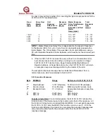
in Figure 4-A for the switch assignments. The settings for the WARN and
ALARM outputs have been covered in Section 3.3. The time delay specifies the
amount of time a WARN condition persists before an ALARM condition will occur.
8
7
6
5
4
3 & 4
3
8
7
6
5
4
3 & 4
15. WARN normally de-energized
14. WARN normally energized
13. ALARM normally de-energized
12. ALARM normally energized
11. WARN latching
10. WARN non-latching
9. ALARM latching
8. ALARM non-latching
7. 8 Second ALARM Time Delay
6. 4 Second ALARM Time Delay
5. 2 Second ALARM Time Delay
4. 1 Second ALARM Time Delay
OFF
Option
Figure 4-A Dip Switch Options
1. 100% Sens - 1 sqft @ 50 ft
2. 75% Sens - 1 sqft @ 35 ft
2
2
3. 50% Sens - 1 sqft @ 25 ft
1
ON
1 & 2
1

