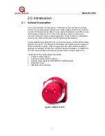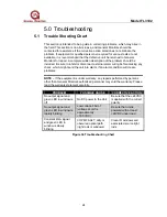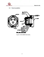
Model FL3102
21
PIN 1
2
1
4
36
5
OP
E
N
8
7
PIN 1
3
2
1
ON
8
6
7
5
4
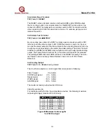
3.5 Switch Selectable Options
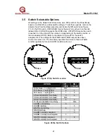
All settings on the Model FL3102 are done via a DIP-switch on the Power/Relay
board or via RS-485 (overrides switch settings). To set these options, remove the
detector head from the Base Assembly and locate the DIP-switch (see Figure
27). On the DIP-switch, ON/CLOSED means the switch is pushed in on the side
labeled ON or CLOSED (opposite the OPEN side). OFF/OPEN means the switch
is pushed in on the side with the number corresponding to the switch position or
the side labeled OPEN. (Refer to the tables in Figure 28 for the switch
assignments.) The settings for the WARN and ALARM outputs have been
covered in section 3.4. The time delay specifies the amount of time a WARN
condition persists before an ALARM condition will occur.
Figure 27 Dip Switch Location
OPTION
OFF /
OPEN
ON /
CLOSED
100% Sens – 1 sqft @ 50 ft
1&2
75% Sens – 1 sqft @ 35 ft
2
1
50% Sens – 1 sqft @ 25 ft
1
2
2-Second ALARM Time Delay
3
4
4-Second ALARM Time Delay
3&4
8-Second ALARM Time Delay
4
3
10-Second ALARM Time Delay
3&4
ALARM non-latching
5
ALARM latching
5
WARN non-latching
6
WARN latching
6
ALARM normally energized
7
ALARM normally de-energized
7
WARN normally energized
8
WARN normally de-energized
8
Figure 28 Dip Switch Options

