Model FL3102
34
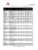
R - indicates Read Only Access
R/W - indicates Read/Write Access
Parameter
Function
Type
Scale
Access
REG
Addr
Master
I/O
Addr
Refer to
Section
Comm 1 Only
Total Receive
Errors
Total # of Comm 1 Only
Receive Errors
Value 8-Bit R
0024 40037 7.7.23
Comm 1 & 2
RXD CRC Lo
Errors
Total # of RXD CRC Lo
Errors (Comm 1 & 2)
Value
8-Bit
R
0025
40038
7.7.24
Comm 1 & 2
RXD CRC Hi
Errors
Total # of RXD CRC Hi
Errors (Comm 1 & 2)
Value 8-Bit R
0026 40039 7.7.25
Comm 1 Only
Overrun Errors
Total # of Overrun Errors
(Comm 1 Only)
Value
8-Bit
R
1027
40040
7.7.26
Comm 1 Only
Noise Flag
Errors
Total # of Noise Flags
Errors (Comm 1 Only)
Value 8-Bit R
0028 40041 7.7.27
Comm 1 & 2
Framing Errors
Total # of Framing
Errors (Comm 1 & 2)
Value
8-Bit
R
0029
40042
7.7.28
Comm 1 & 2
Message
Interval
Indicates Comm 1 or 2
Message Interval in Milli-
seconds
Value 8-Bit R
002A 40043 7.7.29
Comm 2 Only
Total Receive
Errors
Total # of Comm 2 Only
Receive Errors
Value
8-Bit
R
002B
40044
7.7.30
Comm 1 Only
SCI Interrupt
Errors
Total # of Serial Comm
Interface Errors (Comm 1
Only)
Value 8-Bit R
002C 40045 7.7.31
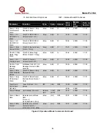
Clear Comm
1 & 2 Errors
Clear All Comm 1 & 2
Errors
Bit
1-Bit
R/W
002D
40046
7.7.32
Not Used
002E
40047
Comm 2 Address
Unit Address (Comm 2)
Decimal
Hex
(1-247)
(01-F7)
R/W
002F
40048
7.7.33
Comm 2 Baud
Rate
Indicates present Baud
Rate
(Comm 2)
(2400, 4800, 9600, 19.2K)
Value (0-3) R/W
0030 40049 7.7.34
Comm 2 Data
Format
Indicates present Data
Format (Comm 2)
(8N-1, 8E-1, 8O-1, 8N-2)
Value
(0-3)
R/W
0031
40050
7.7.35
Figure 40 Operational Mode Commands Continued

