39
Model FL4000H
4.0 Modbus Interface
4.1 Introduction
The FL4000H provides communicating ability via the industry standard Modbus protocol, while
acting as the slave device in a typical master/slave configuration. Upon receiving an
appropriate query from the master, the FL4000H will respond with a formatted message as
defined below.
4.2 Communication Slave Address
The FL4000H communication slave address is a unique ID used by the Modbus protocol to
identify each unit on a multi drop Modbus communication bus. The address may contain the
values 1 – 247. There are two communication channels on the FL4000H. Each channel may
have a separate slave address. The default slave address for each channel is 1. Register 0x09
is used to modify the address for channel COM1 and register 0x2F is used to modify the
address for channel COM2.
4.3 Baud Rate
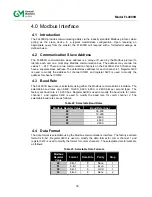
The FL4000H baud rate is selectable using either the Modbus communications interface. The
selectable baud rates are 38,400, 19,200, 9,600, 4,800, or 2,400 bits per second (bps). The
factory set baud rate is 19,200 bps. Register 0x0B is used to modify the baud rate for comm
channel 1 and register 0x30 is used to modify the baud rate for comm channel 2. The
selectable baud rates are as follows:
Table 22: Selectable Baud Rates
Modbus Register Value
Baud Rate (bps)
04
38,400
03
19,200
02
9,600
01
4,800
00
2,400
4.4 Data Format
The data format is selectable using the Modbus communications interface. The factory set data
format is 8-N-1. Register 0x0C is used to modify the data format for comm channel 1 and
register 0x31 is used to modify the format for comm channel 2. The selectable data formats are
as follows:
Table 23: Selectable Data Formats
Modbus
Register
Value
Format
Data Bits
Parity
Stop
00
8-N-1 8 None
1
01
8-E-1 8 Even
1
02
8-O-1 8 Odd
1
03
8-N-2 8 None
2
Summary of Contents for FL4000H
Page 2: ...ii Model FL4000H This page intentionally left blank ...
Page 8: ...viii Model FL4000H Figure 2 Mounting Instruction Figure 3 Wall Mounting Assembly ...
Page 28: ...28 Model FL4000H Figure 16 Detector Mounting and Installation ...
Page 61: ...61 Model FL4000H 6 2 Final Assembly Figure 26 FL4000H Cross Section View ...

