44
Model FL4000H
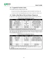
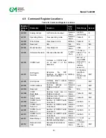
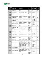
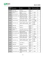
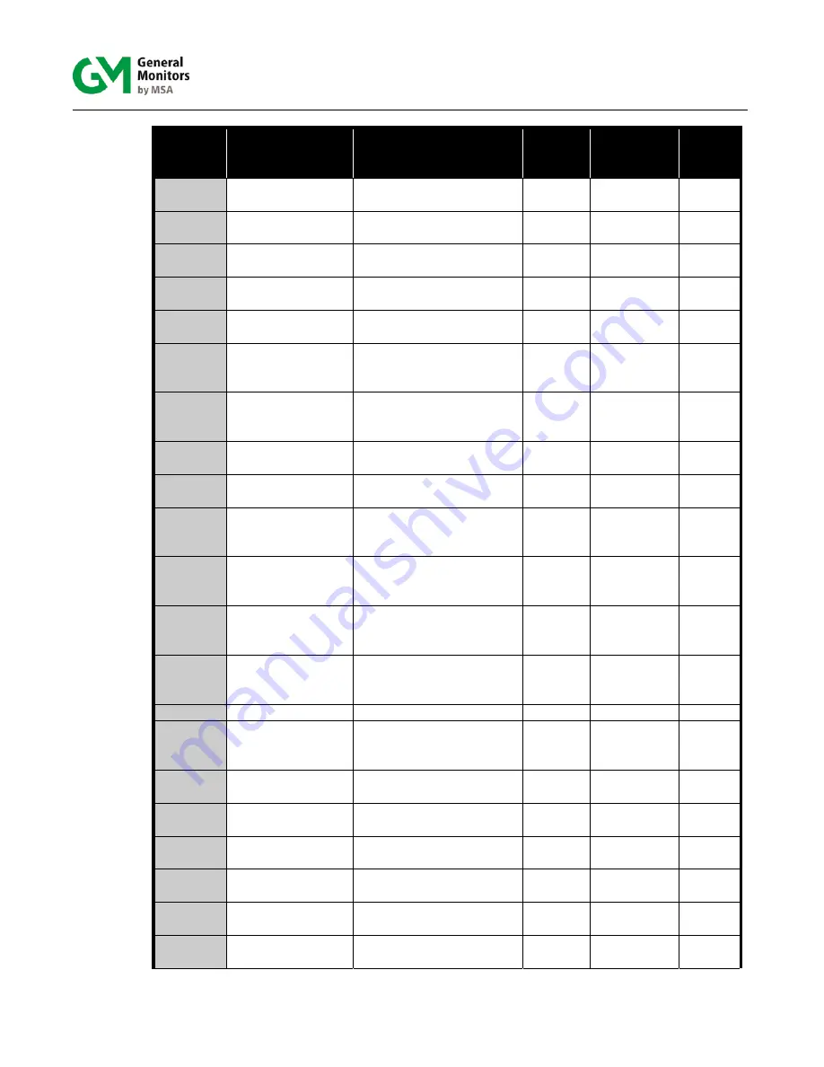
Register
Address
(Hex)
Parameter
Function
Data
Type
Data Range Access
0x0013
Clear COPM Fault
Counts
Reset COPM Counters to
zero.
Bit Map
Bit 1 =
Reset
W
0x0014
Sensor
Temperature
Temperature in
Degrees C
Numeric
Value
-128… +128 R
0x0015 –
0x001C
Reserved N/A
N/A
N/A N/A
0x001D
HART
Enable/Disable
Enable/disable HART
Numeric
Value
0 - disable
1 - enable
R/W
0x001E –
0x001F
Reserved N/A
N/A
N/A N/A
0x0020
COM1 or COM2
Total Receive
Errors
Number of receive errors
on user Modbus
Numeric
Value
0-65535 R
0x0021 Data
Errors
Number of illegal data
write errors on user
Modbus
Numeric
value
0-65535 R
0x0022
Function Code
Errors
Number of function code
errors on user Modbus
Numeric
Value
0-65535 R
0x0023
Starting address
errors
Number of starting
register address errors
Numeric
Value
0-65535 R
0x0024
Total COM1 Only
Receive Errors
Total communication
errors received on Comm
1
Numeric
value
0-65535 R
0x0025
CRC errors LO for
serial channel
Number of CRC LO
errors on user Modbus
channels
Numeric
value
0-65535 R
0x0026
CRC errors HI for
user serial
channel
Number of CRC HI errors
on user Modbus channels
Numeric
value
0-65535 R
0x0027
Total Overrun
Errors COM1 Only
Total Overrun errors
received on comm
channel 1
Numeric
value
0-65535 R
0x0028 Reserved
N/A
N/A
N/A
N/A
0x0029
Total Framing
Errors COM1 &
COM2
Total Framing errors
received on comm
channels 1 & 2
Numeric
value
0-65535 R
0x002A-
0x002C
Reserved N/A
N/A
N/A N/A
0x002D
Clear Serial COM
Errors
Clear Modbus
communication errors
Numeric
Value
1 W
0x002E
HART small
current
Enable/disable 1.25mA
HART minimum current
Numeric
Value
0 – disable
1 - enable
R/W
0x002F COM2
Address
Set/view address on
Modbus channel 2
Numeric
Value
1-247 R/W
0x0030
COM2
Baud Rate
Set/view baud rate on
Modbus channel 2
Numeric
Value
Table 33
R/W
0x0031
COM2
Data Format
Set/view data format on
Modbus channel 2
Numeric
Value
Table 34
R/W
Summary of Contents for FL4000H
Page 2: ...ii Model FL4000H This page intentionally left blank ...
Page 8: ...viii Model FL4000H Figure 2 Mounting Instruction Figure 3 Wall Mounting Assembly ...
Page 28: ...28 Model FL4000H Figure 16 Detector Mounting and Installation ...
Page 61: ...61 Model FL4000H 6 2 Final Assembly Figure 26 FL4000H Cross Section View ...

