TL104
3.0 Use and Operation
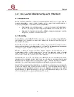
Before beginning a flame detector check, adjust the dipswitch setting in the TL104 test lamp
according to the type of GM flame detector used. Table 1 shows the dipswitch configurations
for GM flame detectors FL3XXX and UV/IR Type VI. Using a fully charged TL104, stand up to
the distance specified in Table 1 from the flame detector to be tested and aim the TL104
directly into the detector window. Press the ON button and ensure the high intensity intermittent
beam strikes the detector face. If the system is operating normally, the control module will go
into a warning condition after a few flashes of the test lamp. If the lamp remains ON for the
period set by the time delay adjustment, the controller will go into alarm
1
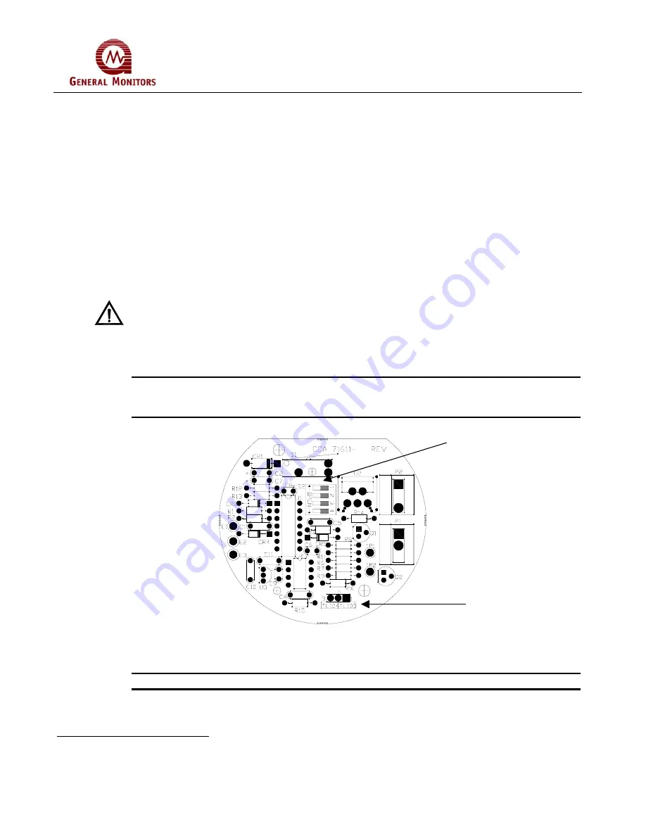
Before testing any GM flame detector, see Table 1 and Figure 1 to assure that dipswitch
settings and mode jumper position are correct for the particular detector.
CAUTION
: When operating in conditions involving fog, rain or frost, UV and IR radiation are
(diminished) with increasing levels of moisture. The moisture level will affect the
potential range of the detector. When using the test lamp in conditions of frost,
make sure that the lens is free of frost and ice. A plastic card can be used without
scratching the lens cap to remove frost build-up.
NOTE
: Recharging the battery and normal docking of the test lamp when not in use is highly
recommended. This will extend the useful life of the battery and also make the test
lamp available for immediate use. Normal recharge time is 14 hours.
Dipswitch
Configuration
Jumper
Figure 1: Functional board located under lamp assembly
NOTE
: The dipswitch settings, as shown in Figure 1, are all open.
1
For test initiation with the FL4000 flame detector, please refer to the FL4000 Instruction Manual.
4

