background image

3.2 Electrical Features: 
 

The POS-002 uses a microprocessor based measurement system. The polarization 
tracking function is continuously monitored and fully automatic. There are no user 
serviceable parts in the system, and no calibration is required.  
 
The POS-002 re 12V/0.5A and 

12V/0.15A DC power supplies. Due to the 

presence of internal high voltages, the following safety precautions must be exercised 
during operation.   


The ground pin on the power cable must be connected to earth ground of the 
power supply.  


Never touch the boards inside the package without proper insulation and 
grounding. 


The POS-002 is not user serviceable and can be serviced only by factory-
authorized personnel.   

 
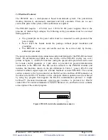
The power and communication connections and pin definitions for the POS-002 are listed 
below. Pin definitions and labels are also shown on the POS-002 overlay (see cover 
picture or Figure 1). An RS-232 interface (using the special cable provided) can be used 
for remote control operation. A 2-part cable is provided for power/communication 
connections to the POS-002. The first section connects to the POS-002 module, and 
includes the functions shown in the pin definition in Table 1: power, RS-232, and 
external feedback signal input (for external feedback version POS-002). The second 
section connects to the 3-pin connector on the first section, and has a DB9 connector on 
the other side for RS-232 interface with a computer. Remote operation can be achieved 
by using any program that supports the RS-232 communication protocol. A simple 
LabView™ (National Instruments, www.ni.com) interface is provided for RS-232 
control. RS-232 control commands are listed in Section 4.4.1, and Section 4.4.4 contains 
a description of the control program. 


Figure 4 POS-002 electrical/communication connector 

1

10


Document #: GP-UM-POS-002-21 


Page 9 of 30 

苏州波弗光电科技有限公司


苏州波弗光电科技有限公司


苏州波弗光电科技有限公司


苏州波弗光电科技有限公司


苏州波弗光电科技有限公司


苏州波弗光电科技有限公司

苏州波弗光电科技有限公司


苏州波弗光电科技有限公司


苏州波弗光电科技有限公司


苏州波弗光电科技有限公司


苏州波弗光电科技有限公司


苏州波弗光电科技有限公司

苏州波弗光电科技有限公司


苏州波弗光电科技有限公司


苏州波弗光电科技有限公司


苏州波弗光电科技有限公司


苏州波弗光电科技有限公司


苏州波弗光电科技有限公司

苏州波弗光电科技有限公司


苏州波弗光电科技有限公司


苏州波弗光电科技有限公司


苏州波弗光电科技有限公司


苏州波弗光电科技有限公司


苏州波弗光电科技有限公司

苏州波弗光电科技有限公司


苏州波弗光电科技有限公司


苏州波弗光电科技有限公司

网址:www.bonphot.com

邮箱:sales@bonphot.com

电话:0512-62828421

Summary of Contents for POS-002

Page 1: ...eneralphotonics com Document GP UM POS 002 21 Page 1 of 30 州 波 弗 光 电 科 技 有 限 公 司 苏 州 波 弗 光 电 科 技 有 限 公 司 苏 州 波 弗 光 科 技 有 限 公 司 苏 州 波 弗 光 电 科 技 有 限 公 司 苏 州 波 弗 光 电 科 技 光 电 科 技 有 限 公 司 苏 州 波 弗 光 电 科 技 有 限 公 司 苏 州 波 弗 光 电 科 技 有 限 波 弗 光 电 科 技 有 限 公 司 苏 州 波 弗 光 电 科 技 有 限 公 司 苏 州 公 司 苏 州 波 弗 光 电 科 技 有 限 公 司 苏 州 波 弗 光 电 科 网址 www bonphot com 邮箱 sales bonphot com 电话 0512 62828421 ...

Page 2: ... please contact General Photonics for assistance If necessary return the defective product freight prepaid clearly labeled with the RMA number with as complete a description of the problem as possible The repaired or replacement product will be returned freight prepaid as soon as possible The above warranty specifically excludes products that have been repaired or modified by non manufacturer auth...

Page 3: ...pect the product and review the manual carefully Make sure that the product is in a secured work environment in terms of temperature humidity electrical power hazard due to fire or shock etc for proper operation Standard laser safety procedures should be followed during operation Document GP UM POS 002 21 Page 3 of 30 州 波 弗 光 电 科 技 有 限 公 司 苏 州 波 弗 光 电 科 技 有 限 公 司 苏 州 波 弗 光 科 技 有 限 公 司 苏 州 波 弗 光 电 ...

Page 4: ...ing 22 4 4 4 LabView control program 22 Section 5 Application Examples 26 5 1 PMD compensation 26 5 2 Polarization Demultiplexing 27 5 3 Coherence detection 29 5 4 Polarization tracking for sensor system 29 Section 6 Technical Support 30 Document GP UM POS 002 21 Page 4 of 30 州 波 弗 光 电 科 技 有 限 公 司 苏 州 波 弗 光 电 科 技 有 限 公 司 苏 州 波 弗 光 科 技 有 限 公 司 苏 州 波 弗 光 电 科 技 有 限 公 司 苏 州 波 弗 光 电 科 技 光 电 科 技 有 限 公 司...

Page 5: ...V 0 5A 12V 0 15A External feedback voltage 0 5 to 4 6V DC ext feedback version only Communications interface4 RS 232 Notes Specifications listed above are for the standard configuration specs may be different for instruments with different wavelength or input power ranges 1 Per user specification when product is ordered 2 Other wavelengths and control algorithms may be available upon request 3 The...

Page 6: ...racker with SM output fiber covers the 1260 1650 nm fiber transmission window A short wavelength custom version can also be made to cover a wavelength range from 970 nm to 1260 nm Versions with PM output typically have a wavelength range of center wavelength 50nm Figure 1 POS 002 polarization tracker module for fiber optic systems The operation of the POS 002 is based on a feedback system as shown...

Page 7: ...illator level interferometer fringe contrast SOP etc In this configuration the polarization monitor unit composed of the components in the dashed line box shown in Figure 2 is not installed In this case the optical path of the entire module is a continuous section of optical fiber Therefore the optical insertion loss from the polarization controller can be disregarded Figure 2 POS 002 polarization...

Page 8: ...t has PM fiber at the input Examples include electro optic modulators or PM coupler combiners The external feedback POS 002 has SM fiber output In this configuration there is no polarizer in the output optical path Therefore the output optical power is a constant Once the tracker is enabled the output SOP will be actively adjusted to optimize the parameter of interest If the feedback signal is set...

Page 9: ...operation A 2 part cable is provided for power communication connections to the POS 002 The first section connects to the POS 002 module and includes the functions shown in the pin definition in Table 1 power RS 232 and external feedback signal input for external feedback version POS 002 The second section connects to the 3 pin connector on the first section and has a DB9 connector on the other si...

Page 10: ... at all times Check optical power level of the input optical beam Make sure the optical power level at the input connector is below 20 dBm 100 mW 4 1 Unpacking Inspect POS 002 to check for any physical damage due to shipping and transportation Contact carrier if any damage is found Check the packing list for any missing parts or accessories Avoid excess vibration environments when using the POS 00...

Page 11: ... the input connector of the POS 002 It is important to clean the fiber connector using industry standard procedures For a high power laser source turn off optical power source before connector cleaning 5 If using external electrical feedback connect the external feedback signal to the POS 002 PIN 8 DC error signal PIN 9 GND Guidelines for electrical error signal Please note that there is no buffer...

Page 12: ...The POS 002 can be serviced only by manufacturer authorized personnel There are no user serviceable components in this system The performance of the POS 002 can be tested with standard polarization measurement instruments or a laboratory setup The output SOP from the POS 002 can be monitored by a commercial polarization analyzer For laboratory testing the user can insert a manual or motorized pola...

Page 13: ...mes with two connection cables One has a 10 pin connector on one side to connect to the POS 002 On the other side of that cable are labeled wires for the power and external signal connections and a 3 pin connector to connect to the RS 232 connection cable The RS 232 connection cable has a matching 3 pin connector on one side to connect to the first cable and a DB9 connector on the other side to co...

Page 14: ... the RS 232 port There are many programming languages that support serial communications including Visual Basic LabView and C Table 2 RS 232 Command List Query Commands Command Description Response IDN Query the Product Number IDN GP POS 002V2 0 E VER Query the Firmware Version VER POS002 V21 020513A version dependent MOD Query operation status MOD ENA POS enabled MOD DIS POS disabled SER Query se...

Page 15: ...is to slow down the effective step time Delay offset 0 5 xxx µs Range 0 59999 Default value 5 Delay xxx DLY Query current delay offset Delay xxx Table 3 Command Response Codes E00 No error Correct command received E01 Undefined Command E02 Missing start character E03 Missing end character E04 Missing parameter E05 Invalid syntax found in command string E06 Invalid mode command E07 String of charac...

Page 16: ...ion state using default control settings and fixed step size mode Figure 7 shows the response of the POS 002 to a single discontinuous change in the input polarization state using the default control parameter settings The red line is the input polarization and the blue line is the POS 002 output The POS 002 compensates for the input polarization change via a series of small polarization steps The...

Page 17: ...ack control loop Command STS xx The step size defines the control voltage increment applied to the polarization controller per control loop cycle in response to a change in feedback signal level The POS 002 uses a 0V 150V voltage output to control the polarization controller This control voltage range is converted to 212 4096 digital steps for the purposes of the control algorithm 1 digital step 1...

Page 18: ... but can also increase noise Figure 10 shows the response of the POS 002 to the same discontinuous change in the input polarization state as in Figure 7 but with a low threshold setting and a step size setting larger than the default value Compared to Figure 7 the total recovery time is smaller but the output polarization fluctuation labeled C in Figure 7 increases Figure 10 POS 002 response to di...

Page 19: ...s made by the controller The DLY command adds a delay offset to the period between a polarization controller step and the next read of the feedback signal increasing the effective cycle time to 26 0 5 xxx 2 yy 1 µs where xxx is the delay setting and yy is the AD average setting Figure 11 POS 002 output delay 100 Figure 12 POS 002 output delay 0 Figure 13 POS 002 response to discontinuous change in...

Page 20: ...al value used for one control loop cycle Increasing the AD average number can improve the stability if the feedback signal is noisy For example setting AD avg 2 converts a 50mV 10KHz noise component in the feedback signal to a 25mV 5KHz noise component Increasing the AD average number also increases the control loop cycle time by the amount specified in the table Figure 14 shows the response of th...

Page 21: ...xx 1 22 mV For example if for a given laser source the POS 002 stabilizes the SOP such that the feedback signal reaches a maximum of 4V then with the threshold level at the default setting as long as the feedback signal remains higher than 4V 0 00122V 3 99878V the POS 002 will not actively change the polarization The threshold control command can be used to reduce the effect of noise If the SOP va...

Page 22: ...iew control program The command list in Table 2 can be used to write control programs for the Pos 002 General Photonics provides a sample control program that can be used as a base for customization by the user The program is written in LabView The source code vi files can be opened and edited using LabView 2012 SP1 or above For users who do not need to customize the control program or do not have...

Page 23: ...f using the VI version of the control program before turning off the instrument The screen layouts for the control programs POS_REMOTE vi source code and POS_REMOTE exe executable are shown below The control port selection menu is located at the top right of the interface screen under the product identification box It displays the selected port for the RS 232 connection If the selected port and th...

Page 24: ...etail on responses to version status query commands Communication Error Indicator light turns on if a communication interruption occurs while the POS 002 is attempting to communicate with the computer Document GP UM POS 002 21 Page 24 of 30 州 波 弗 光 电 科 技 有 限 公 司 苏 州 波 弗 光 电 科 技 有 限 公 司 苏 州 波 弗 光 科 技 有 限 公 司 苏 州 波 弗 光 电 科 技 有 限 公 司 苏 州 波 弗 光 电 科 技 光 电 科 技 有 限 公 司 苏 州 波 弗 光 电 科 技 有 限 公 司 苏 州 波 弗 光 电...

Page 25: ...after Power CK is clicked if the light level is within range Input Light Power Check box Displays POS 002 response to the power check command Response is E00 if light level is within range E08 for power high and E09 for power low Communication Error Indicator light turns on if communication is interrupted while the POS 002 is trying to communicate with the computer Document GP UM POS 002 21 Page 2...

Page 26: ... 002 E DGD Convert error signal into 0 5V feedback signal RX PMD Compensation Scheme 2 Use the receiver to obtain the feedback signal In this scheme the error signal indicating the PMD effect can be a clock signal from the receiver s photodetector or a BER detected before FEC inside the receiver The user converts the error signal into an analog signal between 0 5 and 4 6V volts and feeds it back t...

Page 27: ...l for polarization demultiplexing The BER will be minimized when the two polarization channels are properly separated A simple circuit can be used to convert the BER into a 0 5 to 4 5V feedback signal for the POS 002 E the bigger the voltage the smaller the BER The polarization tracker then automatically maximizes the feedback signal to effectively separate the two polarization channels TX1 TX2 RX...

Page 28: ...tion channels are set at different power levels and the detected power difference is an indication of polarization channel separation A simple circuit can be used to convert the noise channel power difference into a 0 5 to 4 6V feedback signal for the POS 002 E The polarization tracker then automatically maximizes the feedback signal to effectively separate the two polarization channels TX1 TX2 RX...

Page 29: ...A POS 002 E can be used to obtain the maximum detection sensitivity In this application the visibility of the sensor can be monitored with a phase modulator and can be converted into an analog signal between 0 5 and 4 6V to be fed back to the POS 002 E The polarization tracker then automatically maximizes the visibility for stable optimized detection sensitivity SM TX POS 002 I PD PD LO RX Automat...

Page 30: ...e mail at info generalphotonics com General Photonics will respond to all customer questions within 24 hours during regular business hours You can also write to General Photonics 5228 Edison Avenue Chino California 91710 USA 州 波 弗 光 电 科 技 有 限 公 司 苏 州 波 弗 光 电 科 技 有 限 公 司 苏 州 波 弗 光 科 技 有 限 公 司 苏 州 波 弗 光 电 科 技 有 限 公 司 苏 州 波 弗 光 电 科 技 光 电 科 技 有 限 公 司 苏 州 波 弗 光 电 科 技 有 限 公 司 苏 州 波 弗 光 电 科 技 有 限 波 弗 光 电...

Reviews: