background image

Model 88™ 


pedal, and the cable’s rotation against the 
Cable Feeding Tool will work the section 
through the trap.  Never try to force a cable 
through a P-trap smaller than 4” in diameter.  


9.  If the motor begins to slow down or the clutch 

starts to slip, you have probably reached the 
stoppage.  Stop the machine and switch motor 
in reverse.  Run machine for a few seconds.  
Then stop and switch to forward rotation.  
Repeat this procedure until water starts to flow. 
This is often the best way to work through the 
stoppage. 

10. Run the machine in reverse to pull sections out 

of the line.  After the line is opened with a 
Spearhead or 2” U-Cutter, follow with larger 
blades which scrape the inside edges of the 
pipe, assuring a real cleaning job. 


Hint:

 It's often helpful to have a small 

stream of water running in the line to 
wash the cuttings away while the 
machine is in operation and after. 

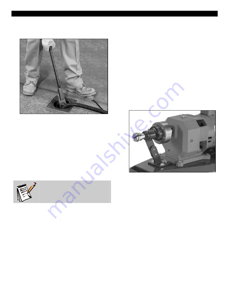
FOLDING HANDLE 

To make the Hot-Rodder more compact, it is 
equipped with a folding handle.  By lifting up the 
sliding collars on each side of the handle, you can 
fold it forward.  When the handle is raised, the 
collars will drop into position, locking the handle in 
place. 

SAFETY CLUTCH 

The safety clutch is located between the motor and 
the Cable Drive Coupler.  It is designed to protect 
your cables from breakage and is factory preset to 
slip at 100 in. lbs. of torque.  Under normal usage 
of your machine, no adjustments need to be made 
to the clutch.  If you find it necessary to change the  

clutch tension, the following procedure should be 
used: 
1.  Remove the clutch cover and loosen the screw 

in the large hex nut on the front of the clutch.  
Turn the nut in to increase tension and out to 
reduce it.  Then tighten the screw. 

2.  If you do not intend to change the tension on 

the clutch very often, you can fold over one of 
the metal tabs on the washer between the nut 
and the body of the clutch so that it presses 
firmly on the hex nut.  You can, of course, alter 
the pressure on the clutch at a later date by 
bending the tab back up, adjusting the nut, and 
bending a different tab against the nut. 

3.  Remember that the clutch is put on the machine 

to protect your cables!  Therefore, do not 
tighten to the point where sections will be 
damaged before the clutch slips. 


GEAR REDUCER 

Model 88 gear reducers are filled with lubricant to 
the proper level before leaving the factory.  Should 
it become necessary to remove the lubricant in the 
field, the following steps should be followed for 
refilling: 
1.  Remove the Vent/Fill plug at the top of the gear 

reducer. 

2.  Remove the Level plug at the middle of the side 

of gear reducer. 

3.  Use a funnel or other device to add lubricant 

until it appears at the side opening (Capacity: 
1.25 pints). 

MAINTENANCE 

To keep your machine operating smoothly, it is 
essential that all bearings and bushings be 
lubricated.  Oiling moving parts is particularly 
important where machine comes in contact with 
sand, grit, and other abrasive material. 


6

Summary of Contents for 88

Page 1: ...ver no machine is better than its operator We therefore suggest you read these instructions through carefully before using your machine on the job This will enable you to operate the Model 88 more efficiently and more profitably Failure to follow these instructions may cause personal injury to operator or damage to equipment SAVE THESE INSTRUCTIONS ...

Page 2: ...ol Electrical Safety 1 Grounded tools must be plugged into an outlet properly installed and grounded in accordance with all codes and ordinances Never remove the grounding prong or modify the plug in any way Do not use any adapter plugs Check with UL approved tester or a qualified electrician if you are in doubt as to whether the outlet is properly grounded If the tool should electrically malfunct...

Page 3: ...ork by hand or against your body is unstable and may lead to loss of control 2 Do not force tool Use the correct tool for your application The correct tool will do the job better and safer at the rate for which it is designed 3 Do not use tool if switch does not turn it on or off Any tool that cannot be controlled with the switch is dangerous and must be repaired 4 Disconnect the plug from the pow...

Page 4: ...ptacle is properly grounded Test the GFCI before each use 1 Plug into 120 volt receptacle 2 Push test button Indicator light will go out and power to machine should cut off 3 If light does not go out when test button is pushed equipment should not be used until proper repairs can be made 4 To restore power after test push reset button With the reset button depressed if the machine doesn t start st...

Page 5: ...le connector of the cable to the machine by twisting the knurled ring on the Cable Drive Coupler until the plunger pin clicks into place On machines using L cables twist the cable until the plunger pin springs out 5 Pull the machine back until the slack is out of the cable With the motor switch in the Forward position and while standing behind the machine press down on the switch mounted on the ha...

Page 6: ...f your machine no adjustments need to be made to the clutch If you find it necessary to change the clutch tension the following procedure should be used 1 Remove the clutch cover and loosen the screw in the large hex nut on the front of the clutch Turn the nut in to increase tension and out to reduce it Then tighten the screw 2 If you do not intend to change the tension on the clutch very often yo...

Page 7: ...olts 4 88 301 Motor 1725 RPM Disc See 88 300 1 88 130 Front Bearing Post 88 301 1 Motor 3450 RPM 88 130 A Bushings 2 88 301 2 Motor 1750 RPM 88 130 B Grease Fitting 88 302 1 Gear Head Only 7 to 1 Ratio 88 130 C Post Adjusting Bolts 2 88 302 2 Gear Head Only 3 5 to 1 Ratio 88 131 Post Bolts Nuts Washers 3 88 302 A Gear Head Vent Cap 88 150 1 Handle Hinge Assembly 88 302 1 A Gear Head Vent Cap 88 15...

Reviews: