8
Booster Power Supply Manual
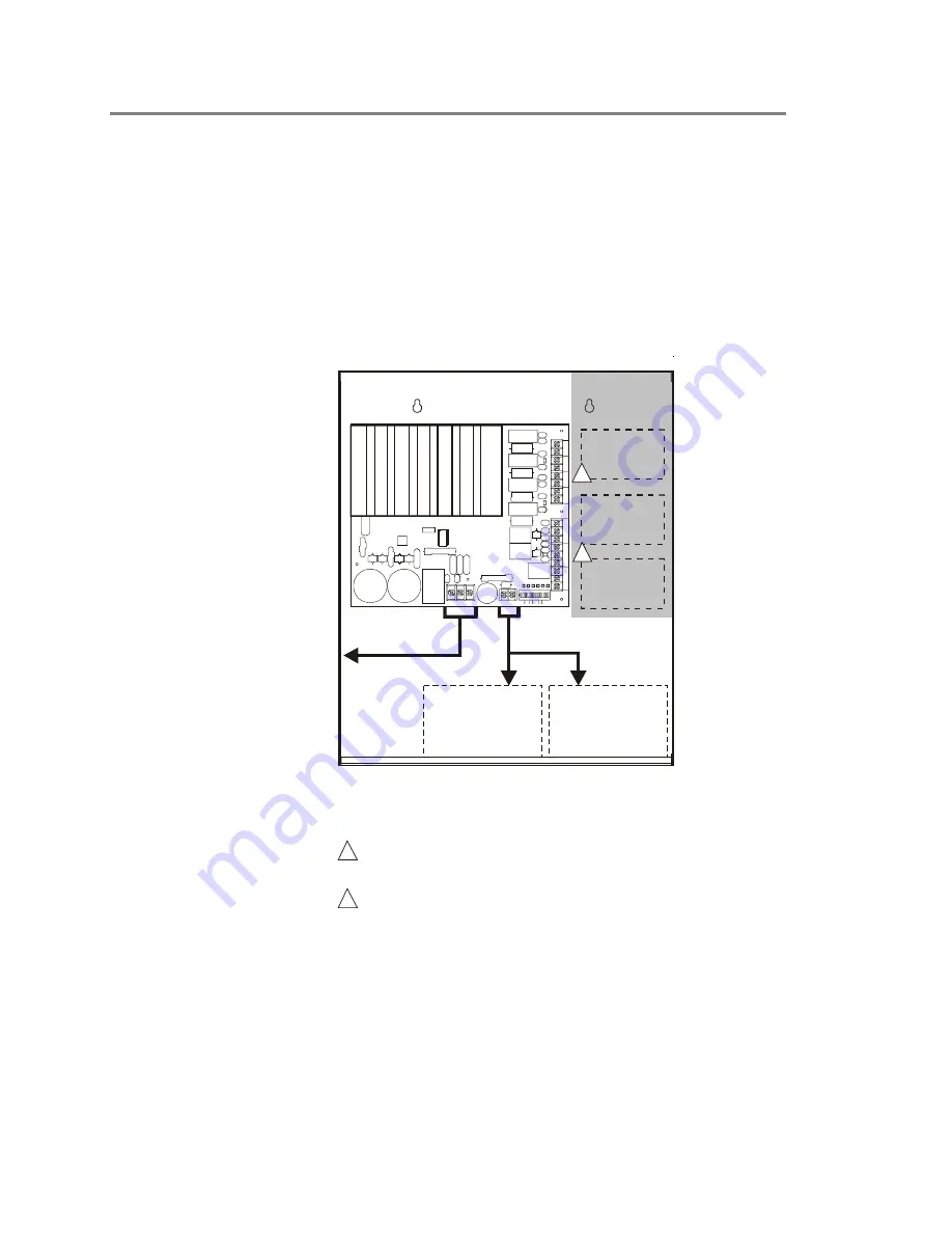
Wiring the Booster Power Supply
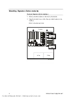
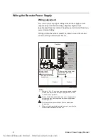
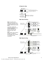
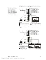
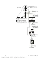
Wiring placement
To avoid noise, keep input wiring isolated from high current
output and power limited wiring. Separate high current
input/output from low current. Separate power limited from non-
power limited wiring.
Wiring within the cabinet should be routed around the cabinet,
not across the printed circuit board.
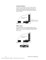
Backbox
Booster Power Supply
Battery
(non-power limited &
supervised)
Route AC supply
through these
knockouts only
Battery
Battery wiring (non-power
limited & supervised)
power limited
wiring area
[Wire route.cdr]
L
N
G
+ BATT ER Y -
SW
1
NC
TR
O
U
B
L
E
CO
M
N
O
O
UT
SEN
S
E
2
CO
M
IN
O
U
T
SEN
SE 1 CO
M
IN
-
NA
C4
+-
NA
C3
+-
NA
C2
+-
NA
C1
+
NA
C
1
NA
C
2
NA
C
3
NA
C
4
BA
T
GN
D
ABRATEAC AUX
1 2 3 4 5 6 7 8 9 10 1112
S1 S2
P3
P2
SW1
1
P4
P1
Notes:
1.
Maintain 1/4 in. (6 mm) spacing between power limited
and non-power limited wiring or use type FPL, FPLR,
or FPLP cable per NEC.
2
Power limited and supervised when
configured as
auxiliary power.
.
3
Source must be power limited. Source determines
supervision.
4.
When using larger batteries, make sure to position the
battery terminals towards the door.
not
Non-supervised when configured as
auxiliary power
Signature
Module
Signature
Module
Signature
Module
2
3
Technical Manuals Online! - http://www.tech-man.com


