Booster Power Supply Manual
9
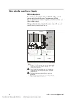
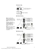
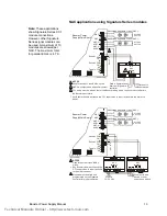
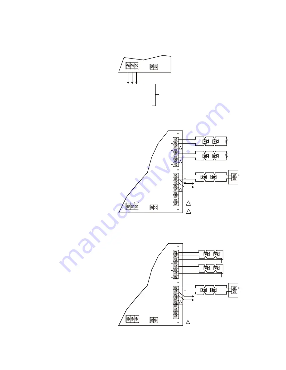
AC power wiring
L N G
+
Battery
-
P3
P4
Booster Power
Supply Main Board
To dedicated 120 VAC
50/60 Hz branch circuit
or
220/230/240 VAC
50/60 Hz branch circuit
(-220 models only)
250 watts for 6.5 amp Booster
375 watts for 10 amp Booster
[Power.CDR]
Per the NEC, no field wiring can
have a potential greater than 150 Vac
with respect to earth ground.
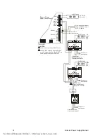
NAC Class B wiring
L N G
+
Battery
-
OUT
OUT
NC
Sense 1
Sense 2
Trouble
COM
COM
COM
IN
IN
NO
NAC1
NAC2
NAC3
NAC4
+
+
+
+
+
+
P3
P2
P4
P1
Booster Power
Supply Main Board
Existing fire
alarm panel
notification
circuit
NAC
UL Listed
EOL 15 K
UL Listed
EOL 15 K
Notification Appliance Circuit (NAC)
Notification Appliance Circuit (NAC)
To next signaling
device or NAC
end-of-line resistor
1
1
2
NOTES:
Used for another Class B NAC circuit.
Used to connect another input circuit
or signaling device.
1
2
[NAC Class B.CDR]
NAC Class A wiring
[NAC Class A.CDR]
Notification
Appliance
Circuit (NAC)
Notification
Appliance
Circuit (NAC)
NOTES:
Used to connect another input circuit
or signaling device.
L N G
+
Battery
-
OUT
OUT
NC
Sense 1
Sense 2
Trouble
COM
COM
COM
IN
IN
NO
NAC1
NAC2
NAC3
NAC4
+
+
+
+
P3
P2
P4
P1
Booster Power
Supply Main Board
Existing fire
alarm panel
notification
circuit
NAC
To next signaling
device or NAC
returning to existing
fire alarm panel
1
1
+
+
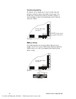
Note 1:
A trouble on the
Booster will be sensed on the
existing fire panels NAC circuit
causing an NAC trouble on that
panel.
In an alarm condition, the
Booster will allow NAC current
to move downstream to
devices connected to the
existing fire panel’s NAC
circuit.
Note 2:
Refer to the connected
fire alarm control panel’s
documentation for more details
on making NAC wiring
connections.
Technical Manuals Online! - http://www.tech-man.com


