Booster Power Supply Manual
13
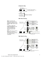
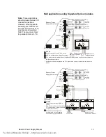
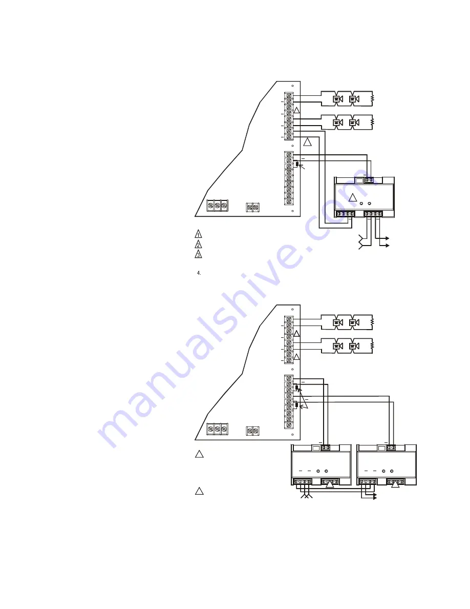
NAC applications using Signature Series modules
E
O
L 47 K
2
NOTES:
Used for another Class B NAC circuit.
NAC4 is configured as an auxiliary output.
CC1 wiring must be within 3 feet of the Booster wiring and in conduit or mounted within
the Booster's enclosure.
Any Booster trouble will cause the CC1 supervision to report a trouble to the main fire
panel.
[APP-05.CDR]
4
8
3
7
2
6
10
1
5
9
CC1
Module
3
Data in from previous
device or Signature
controller
Data out to
next device
L N G
+
Battery
-
OUT
OUT
NC
Sense 1
Sense 2
Trouble
COM
COM
COM
IN
IN
NO
NAC1
NAC2
NAC4/
AUX2
NAC3/
AUX1
+
+
+
+
P3
P2
P4
P1
Booster Power
Supply Main Board
UL Listed
EOL 15 K
UL Listed
EOL 15 K
Notification Appliance Circuit (NAC)
Notification Appliance Circuit (NAC)
1
+
+
+
+
+
Riser out to next
device or riser
supervisory device
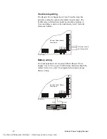
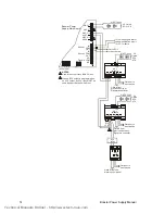
NOTES:
Used for another Class B NAC
circuit.
Any Booster trouble will cause the
CC1 supervision to report a trouble
to the main fire panel.
Modules must be wired and
programmed on the Signature
controller for proper operation.
1
3
2.
[APP-06.CDR]
L N G
+
Battery
-
OUT
OUT
NC
Sense 1
Sense 2
Trouble
COM
COM
COM
IN
IN
NO
NAC1
NAC2
+
+
+
+
P3
P2
P4
P1
Booster Power
Supply Main Board
1
UL Listed
EOL 15 K
UL Listed
EOL 15 K
Notification Appliance Circuit (NAC)
Notification Appliance Circuit (NAC)
1
1
4
8
3
7
2
6
10
1
5
9
CC1
Module
4
8
3
7
2
6
10
1
5
9
CC1
Module
E
O
L 47
K
Riser in
12 - 24 Vdc
3
3
+
+
+
+
+
+
+
+
NAC4/
AUX2
NAC3/
AUX1
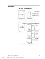
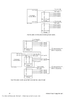
Note:
These applications
show Signature Series CC1
module connections.
However, other Signature
Series signal modules can
be used. A
maximum of 10
modules are allowed per
NAC. The maximum total
for parallel EOL’s is 4.7 K.
Technical Manuals Online! - http://www.tech-man.com


