background image

2

Booster Power Supply Manual

Specifications

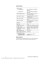
AC line voltage:

6.5 amp Booster

10 amp Booster

120 V / 220/240 Vac (50/60 Hz)
250 watts

120 V / 220/240 Vac (50/60 Hz)
375 watts

Sense voltage V (input)

10 V – 45 V DC or 14 V - 32 V
FWR (unfiltered DC)

Sense current I (input)

6 mA @ 24 Vdc, 3 mA @ 12 Vdc,
12 mA @ 45 Vdc

NAC output voltage

24 V nominal 

(special application output

use only)

NAC output current

3.0 A max. per circuit, 10 A/6.5 A
max total all NACs

Wire size

18 - 12 AWG

NAC EOL

15 K

Auxiliary supv. current

6 amps max. (3 amps max./circuit)

Auxiliary outputs

2 (programmable), replaces NACs

Auxiliary outputs disabled
under battery

Optional – programmable after 30
seconds

Battery Requirements

Up to 10 AH

Battery charger current limit

1.0 A max.

Operating environment:

Operating temperature
Operating humidity

32 to 120

O

 F (0 to 49

O

 C)

0 to 93% RH

LED indicators

The Booster has six LED indicators. There are four NAC trouble
LEDs, one battery trouble LED, and one ground fault LED.

Technical Manuals Online! - http://www.tech-man.com

Summary of Contents for BPS10

Page 1: ...General Signal Building Systems Corporation reserves the right to make product improvements and change product specifications at any time While every precaution has been taken during the preparation of this manual to ensure the accuracy of its contents General Signal Building Systems Corporation assumes no responsibility for errors or omissions FCC WARNING This equipment can generate and radiate r...

Page 2: ... Jumper configuration 7 Wiring the Booster Power Supply 8 Wiring placement 8 AC power wiring 9 NAC Class B wiring 9 NAC Class A wiring 9 Trouble relay wiring 10 Battery wiring 10 Applications 11 NAC circuit power applications 11 NAC applications using Signature Series modules 13 Battery calculation worksheet 15 24 Vdc Notification Appliance Circuit NAC specifications 16 Technical Manuals Online ht...

Page 3: ...0220 10 Amp Booster Power Supply MIRBPS10C 10 Amp Booster Power Supply XLS BPS10 10 Amp Booster Power Supply XLS BPS10220 10 Amp Booster Power Supply XLS BPS10C 10 Amp Booster Power Supply Description The 10 Amp and 6 5 Amp Booster Power Supplies BPS are designed to extend a fire alarm panel s signaling capacity The Booster can be connected to existing Class A or Class B Notification Appliance Cir...

Page 4: ...uit 10 A 6 5 A max total all NACs Wire size 18 12 AWG NAC EOL 15 KΩ Auxiliary supv current 6 amps max 3 amps max circuit Auxiliary outputs 2 programmable replaces NACs Auxiliary outputs disabled under battery Optional programmable after 30 seconds Battery Requirements Up to 10 AH Battery charger current limit 1 0 A max Operating environment Operating temperature Operating humidity 32 to 120 O F 0 ...

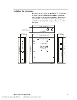
Page 5: ...cation A dedicated 120 Vac 220 240 Vac 50 60 Hz circuit is required for power Install all conduit and pull all wiring into the backbox before proceeding 7 00 17 78 cm 13 00 33 02 cm 13 00 33 02 cm 17 00 43 2 cm 17 00 43 2 cm 17 00 43 2 cm 3 375 8 6 cm 3 50 8 9 cm 3 50 8 9 cm Front View All knockouts for 3 4 conduit 1 9 cm Side View Side View Top View Backbox cdr Technical Manuals Online http www t...

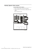
Page 6: ...o the drawing below Backbox Mounting brackets Booster Power Supply Battery Battery MODMOUNT cdr L N G BATTER Y SW1 N C TROUBLE CO M N O OUT SENSE 2 CO M IN OU T SENSE 1 CO M IN NAC4 NAC3 NAC2 NAC1 NAC1 NAC2 NAC3 NAC4 BA T GND ABRA TEAC AUX 1 2 3 4 5 6 7 8 9 10 11 12 S1 S2 P3 P2 SW1 1 P4 P1 4 8 3 7 2 6 10 1 5 9 TB1 TB3 4 8 3 7 2 6 10 1 5 9 TB1 TB3 Signature module Signature module Technical Manuals...

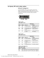
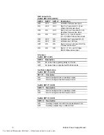
Page 7: ...tivates all NACs Activates both NACs 1 2 and 3 4 ON OFF Activates NAC1 only Activates NAC 1 2 OFF ON Activates NACs 1 2 only Activates NAC 1 2 ON ON Activates NACs 1 2 3 only Activates both NACs 1 2 and 3 4 Sense 2 input Switch SW1 3 4 S2 Description SW1 3 SW1 4 Class B Class A OFF OFF Activates all NACs Activates both NACs 1 2 and 3 4 ON OFF Activates NACs 2 3 4 only Activates NAC 3 4 OFF ON Acti...

Page 8: ...nse input ON ON ON NACs 1 2 3 are 120 bpm NAC4 follow sense input AC power Switch SW1 9 AC SW1 9 Description ON AC power loss reporting delay is 6 hours OFF AC power loss is reported within 20 seconds Auxiliary output setup Switch SW1 10 AUX SW1 10 Description ON NAC3 configured as an auxiliary output OFF NAC3 configured as NAC output circuit Switch SW1 11 AUX SW1 11 Description ON NAC4 configured...

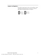
Page 9: ...are used to select a Class A or Class B NAC wiring configuration Both jumpers must be positioned to match the SW1 5 DIP switch selection Class A or Class B Class A Class A Class B Class B JP1 JP2 1 1 2 2 3 3 Jumper CDR Technical Manuals Online http www tech man com ...

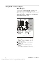
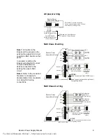
Page 10: ...ower limited wiring area Wire route cdr L N G BATTER Y SW1 N C T RO UBLE CO M N O O UT SENSE 2 COM IN OU T SENSE 1 CO M IN NAC4 NAC3 NAC2 NAC1 NAC1 NAC2 NAC3 NAC4 BA T GND ABRA TEAC AUX 1 2 3 4 5 6 7 8 9 10 1112 S1 S2 P3 P2 SW1 1 P4 P1 Notes 1 Maintain 1 4 in 6 mm spacing between power limited and non power limited wiring or use type FPL FPLR or FPLP cable per NEC 2 Power limited and supervised wh...

Page 11: ...ther Class B NAC circuit Used to connect another input circuit or signaling device 1 2 NAC Class B CDR NAC Class A wiring NAC Class A CDR Notification Appliance Circuit NAC Notification Appliance Circuit NAC NOTES Used to connect another input circuit or signaling device L N G Battery OUT OUT NC Sense 1 Sense 2 Trouble COM COM COM IN IN NO NAC1 NAC2 NAC3 NAC4 P3 P2 P4 P1 Booster Power Supply Main ...

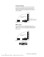
Page 12: ...4 BAT GND AB RATE AC AUX 1 2 3 4 5 6 7 8 9 101112 S1 S2 P3 P2 P4 Booster Power Supply Main Board To Booster trouble monitoring device Trouble CDR Battery wiring Two backup batteries are required with the Booster Power Supply Use 12 Vdc up to 10 AH batteries Batteries should be replaced every five years The diagram below depicts proper battery wiring L N G BATTERY SW1 NC TROUBLE COM NO OUT SENSE 2 ...

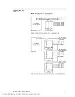
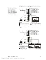
Page 13: ... output 1 NAC output 1 NAC output 2 NAC output 2 NAC output 2 NAC output 3 NAC output 3 NAC output 4 NAC output 3 NAC output 4 NAC output 4 Sense 1 Input Sense 1 Input Sense 1 Input Fire Alarm Control Panel Booster Power Supply Booster Power Supply Booster Power Supply NAC Circuit To next signaling device booster or EOL resistor To next signaling device booster or EOL resistor To next signaling de...

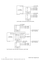
Page 14: ...utputs activate when input NAC 1 activates based on programming All 5 outputs activate when input NAC 2 activates based on programming Fire Alarm Control Panel Booster Power Supply NAC Circuit NAC Circuit To next signaling device booster or EOL resistor To next signaling device booster or EOL resistor To next signaling device booster or EOL resistor Sense 1 Input Sense 2 Input NAC output 1 NAC out...

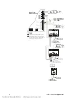
Page 15: ...Appliance Circuit NAC 1 Riser out to next device or riser supervisory device NOTES Used for another Class B NAC circuit Any Booster trouble will cause the CC1 supervision to report a trouble to the main fire panel Modules must be wired and programmed on the Signature controller for proper operation 1 3 2 APP 06 CDR L N G Battery OUT OUT NC Sense 1 Sense 2 Trouble COM COM COM IN IN NO NAC1 NAC2 P3 ...

Page 16: ...T OUT NC Sense 1 Sense 2 Trouble COM COM COM IN IN NO NAC1 NAC2 P3 P2 P4 P1 Booster Power Supply Main Board 1 1 1 Data out to next device Data out to next device Data out to next device Data in from previous device or Signature controller Data in from previous device or Signature controller Data in from fire alarm control panel NAC Circuit NAC Circuit 4 4 8 8 3 3 7 7 2 2 6 6 10 10 1 1 5 5 9 9 CC1 ...

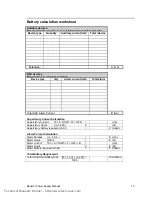
Page 17: ...ce type Qty Alarm current mA Total alarm Total NAC Alarm Current B mA Supervisory Current Calculation Supervisory current 70 A if SW1 12 OFF mA Supervisory Hours i e 24 60 X Hr Supervisory battery required mAHr C mAHr Alarm Current Calculation Alarm Minutes i e 5 min D min Alarm Hours D 60 E Hr Alarm current 190 A if SW1 12 OFF B mA Alarm Hours X E Hr Alarm battery required mAHr F mAHr Total Batte...

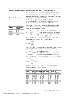
Page 18: ...table the maximum allowable length D of any listed wire gauge pair is determined as follows Rmax D Distance in feet D X 1000 Rmax Maximum allowable wire resistance R 1000 PAIR R 1000 PAIR wire resistance per 1000 pair Using this formula the maximum length of a loaded 2 5 A NAC using a pair of 14 AWG wires is 0 76 146 1 X 1000 5 2 146 feet is the maximum length of a loaded 2 5 A NAC branch circuit ...

Reviews: