background image

PLACEMENT WITHIN THE SHOP / 
ESTABLISHING A SAFETY ZONE

PLACEMENT WITHIN THE SHOP

This machine should be installed and operated only on a
solid, flat and stable floor that is able to support the
weight of the sander (453 lbs - 206 kgs) and the operator.

Using the dimensions shown as a guideline, plan for pla-
cement within your shop that will allow the operator to
work unencumbered and unobstructed by foot traffic
(either passing shop visitors or other shop workers) or
other tools or machinery.

ESTABLISHING A SAFETY ZONE

For shops with frequent visitors or multiple operators, it is
advisable to establish a safety zone around shop ma-
chinery. A clearly defined “no-go” zone on the floor
around each machine can help avoid accidents that
could cause injury to either the operator or the shop visitor. It is advisable to take a few moments to either paint
(using non-slip paint) or using tape, define on the floor the limits or perimeter of each machines safety zone. Take
steps to ensure that all operators and shop visitors are aware that these areas are off limits whenever a machine is
running for everyone but the individual operating the unit.

LIFTING AND HANDLING THE MACHINE

A forklift with steel cable or a hydraulic hand pallet truck
will be required to lift the sander.

Note: Before lifting the sander, unscrew the hex head wood
screws securing the machine to it’s shipping crate 

, using

the supplied 14 mm open end wrench or a 14 mm socket
wrench.

The four 1/2” Hex. bolts and nuts 

are for bolting the sander

to the floor, for optional permanent installation.

SAFETY RULES FOR MACHINE LIFTING

1.

Any equipment used to lift this machine should have 
a rated capacity in excess of 453 lbs (206 kgs).

2.

If using a steel cable, make sure it is strong enough 
so it won’t break during the lifting.

3.

The forklift must only be driven by a licensed driver.

4.

The forks of forklift must protrude beyond the underside of the machine.

5.

Pay special attention to the balance of the machine while lifting. (The motor side is much heavier)

6.

Have another person help guide the way when lifting the machine.

7.

Lower the machine slowly and carefully. Do not let the machine drop or jolt onto the floor.

THIS MODEL 15-010 SANDER IS VERY HEAVY.

TO LIMIT THE RISK OF SERIOUS INJURY OR DAMAGE TO THE MACHINE, READ AND FOLLOW ALL RECOMMENDATIONS BELOW.

9

Summary of Contents for 15-010 M1

Page 1: ...belt tracking Magnetic 2 step safety switch to prevent unwanted or unintentional start up is equipped with an extra large easy access stop panel and a lock out key to prevent unauthorized use of the s...

Page 2: ...for future reference Disclaimer The information and specifications in this manual pertain to the unit as it was supplied from the factory at the time of printing Because we are commit ted to making c...

Page 3: ...der our Standard 2 year Limited Warranty or under our Limited Lifetime Warranty all defective parts components or machinery must be returned freight or postage prepaid to General International or to a...

Page 4: ...10 Install the dust hood end guard 11 Connecting to a dust collector 11 BASIC ADJUSTMENTS CONTROLS 11 Connecting to a power source 11 Magnetic safety switch 12 Overload protection Circuit breaker 12...

Page 5: ...ating 10 Keep hands well away from the sanding belts and all moving parts Use a brush not hands to clear away sanding dust 11 Be sure sanding belts are securely installed on the sanding drums 12 Do no...

Page 6: ...HE MOTOR I D NAMEPLATE A POWER SOURCE WITH GREATER VOLTAGE THAN NEEDED CAN RESULT IN SERIOUS INJURY TO THE USER AS WELL AS DAMAGE TO THE MACHINE IF IN DOUBT CONTACT A QUALIFIED ELECTRICIAN BEFORE CONN...

Page 7: ...DING BELT TRACKING ADJUSTMENT KNOB SANDING BELT TENSION ADJUSTMENT KNOB AUXILIARY TABLE TOP COVER SANDING BELT FRONT TABLE END GUARD DUST HOOD MOTOR ASSEMBLY ON OFF SWITCH FRONT TABLE HEIGHT ADUSTMENT...

Page 8: ...BLE HEIGHT ADJUSTIMENT KNOB 1 4 MM ALLEN KEY 1 5 MM ALLEN KEY 1 6 MM ALLEN KEY 1 12 14 MM OPEN END WRENCH 1 8 10 MM OPEN END WRENCH 1 The front table auxiliary table and dust hood end guard are stored...

Page 9: ...whenever a machine is running for everyone but the individual operating the unit LIFTING AND HANDLING THE MACHINE A forklift with steel cable or a hydraulic hand pallet truck will be required to lift...

Page 10: ...ON THE AUXILIARY TABLE MOUNTING BRACKET 2 Re install the mounting bracket as shown in with the rubber pads against the sander REAR FACE VIEW 1 Remove the two lock knobs located in front of the sander...

Page 11: ...llection CFM require ments for this sander is 1100 CFM If you do not already own a dust collection system consider contacting your General International dis tributor for information on our complete li...

Page 12: ...when working with shorter work pieces periodically adjust the table height to system atically make use of various portions of the belt For example a series of 2 tall workpieces can be separated into 3...

Page 13: ...ING ANY ADJUSTMENT KEEP HANDS WELL AWAY FROM THE SANDING BELT AND ALL MOVING PARTS WHEN THE SANDER IS RUNNING AUXILIARY TABLE UNDERSIDE VIEW Though not essential proper belt tracking having the belt r...

Page 14: ...EPLACEMENT OF THE SANDING BELT Sanding belt should be replaced when worn out Standard size 6 by 108 replacement belts can be purchased in a variety of grits from your General International dealer unde...

Page 15: ...rect belt tension is somewhat subjective It is learned through experience and is somewhat dependant on personal preference A properly tensioned belt will last longer and be much less likely to break p...

Page 16: ...socket wrench then tap on one or both sides of the steel platen to move it either forward or backward until you obtain a gap of 1 8 to 1 4 approx between the steel platen and each of the two rollers...

Page 17: ...formation about our products please visit our website at www general ca SANDING BELTS STANDARD SIZE 6 BY 108 15 011 80 Grit 15 012 100 Grit 15 013 120 Grit DUST COLLECTORS Dust collectors contribute t...

Page 18: ...4 12 07 74 41 07 21 75 39 21 73 12 72 45 25 24 16 09 10 51 52 12 07 54 07 49 63 07 22 50 12 57 71 12 09 12 07 13 11 42 21 34 07 23 37 36 35 31 29 28 29 32 33 30 45 80 21 47 48 46 SA FE TY RU LE S 43 6...

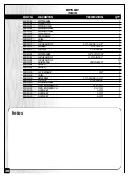
Page 19: ...10 24 SPRING ADJUSTING BLOCK 2 15010 25 SPRING 1 15010 27 LOCK KNOB 5 16 18NCX18X38 2 15010 28 C RING 1 15010 29 BEARING 2 15010 30 TOP COVER 1 15010 31 IDLER ROLLER 1 15010 32 SANDING BELT 1 15010 33...

Page 20: ...6 15010 78 FLAT WASHER 1 2 X32MMX3T 2 15010 80 FLAT WASHER 3 8 X23MMX3T 2 15010 81 HEX HEAD BOLT 3 8 16UNCX1 4 15010 82 HEX HEAD BOLT 10 15010 83 RUBBER PAD 39MMX29X3T 2 15010 84 SPACER 1 15010 85 SP...

Page 21: ...Notes 21...

Page 22: ...al number of the machine and part number Also a brief description of each item and quantity desired 8360 Champ d Eau Montreal Quebec Canada H1P 1Y3 Tel 514 326 1161 Fax 514 326 5565 Parts Service Fax...

Reviews: