background image

10

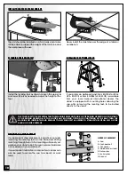
ATTACHING THE LEVELING FEET

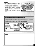
If you prefer, an optional stand (item EX-21BS for EX-16
CE & EX-21CE or item EX-30BS for EX-30CE) is available
from your local General International dealer. The
stand is equipped with mounting holes allowing the
saw, after removing the leveling feet, to be bolted
directly to the stand.

INSTALLING THE OPTIONAL STAND

B

A

Install the leveling feet as shown. Loosen the upper

A

and lower

B

nuts as needed to adjust the height of the

foot.

FOR YOUR SAFETY IT IS ESSENTIAL THAT THE MACHINE DOES NOT ROCK OR TIP DURING OPERATION. UPON START-
UP OR DURING OPERATION, IF YOU NOTICE ANY ROCKING, TIPPING OR CHATTERING OF THE BASE TURN THE
MACHINE OFF IMMEDIATELY AND READJUST THE LEVELING FEET AS NEEDED TO STABILIZE THE SCROLL SAW ON THE
BENCH OR WORK SURFACE

MOUNTING TO A WORK SURFACE

If a permanent shop placement is practical, consider
removing the leveling feet on the base and drilling
matching through holes in the mounting surface of your
workbench or stand to bolt the saw in place (hardware
not included) on your workbench.

If a permanent installation is not practical, clamps can
also be used to secure the saw to a bench or work
table.

The unit should be installed on a flat, sturdy and stable
surface able to support the weight of the machine and
the workpiece with ease.

Never install the machine over the edge of a table or
workbench.

INSTALL THE SAW ON A STABLE SURFACE

ORDER OF ASSEMBLY

D

A

C

E

F

G

B

A- Saw
B- Hex head bolt
C- Flat washer
D- Workbench or stand
E- Flat washer
F- Lock washer
G- Hex nut

Summary of Contents for Excalibur EX-16CE

Page 1: ...32 1 2 358 x 825 mm table surface Organized blade storage on base SPECIFICATIONS LENGTH 27 686 mm EX 16CE 32 812 mm EX 21CE 43 1 4 1100 mm EX 30CE WIDTH 15 380 mm EX 16CE EX 21CE 15 1 2 394 mm EX 30CE HEIGHT 17 432 mm EX 16CE 15 380 mm EX 21CE 15 1 4 387 mm EX 30CE BLADE TILT RANGE 30 LEFT TO 45 RIGHT EX 16CE 38 LEFT TO 45 RIGHT EX 21CE EX 30CE THROAT 16 406 mm EX 16CE 21 535 mm EX 21CE 30 762 mm ...

Page 2: ...nual handy for future reference Disclaimer The information and specifications in this manual pertain to the unit as it was supplied from the factory at the time of printing Because we are commit ted to making constant improvements General Inter national reserves the right to make changes to compo nents parts or features of this unit as deemed necessary without prior notice and without obligation t...

Page 3: ...center or other location designated by General International For further details and assistance contact your local distributor when filing your claim Along with the return of the product being claimed for warranty a copy of the original proof of purchase and a letter of claim must be included a warranty claim form can also be used and can be obtained upon request from General International or an a...

Page 4: ...urface 10 Dust collector outlet 11 Choosing Installing a Saw Blade 11 Blade selection 11 Blade storage 11 Installing or changing blades 13 Operating Instructions 14 On Off switch 14 Adjusting the blade speed 14 Adjusting the blower 14 Workpiece hold down 14 Basic 90º straight or curved cuts 15 Fret cutting 15 Angle or bevel cutting 17 Maintenance Adjustments Servicing 17 Blade clamping thumbscrews...

Page 5: ...use for purposes not intended 12 Avoid working from awkward or off balance posi tions Do not overreach while cutting keep both feet on floor Never lean over or reach behind the blade and never pull the workpiece through the cut from behind 13 Never stand or lean on the saw Serious injury could occur if the unit is tipped over or if the blade is unin tentionally contacted 14 Use of parts and access...

Page 6: ...ration 19 Keep handles dry and free from oil and grease 20 MAINTAIN TOOLS WITH CARE Keep tools sharp and clean for best and safest performance Follow instructions for lubricating and changing acces sories 21 DIRECTION OF FEED Feed work into a blade or cut ter against the direction of rotation of the blade or cutter only 6 1 Material hold down must be properly set and remain in position during use ...

Page 7: ...ersized cord will cause a drop in line voltage resulting in loss of power and overheating The accompanying chart shows the correct size extension cord to be used based on cord length and motor I D plate amp rating If in doubt use the next heavier gauge The higher the number the heav ier the gauge DO NOT MODIFY THE PLUG PROVIDED If it will not fit your receptacle have the proper receptacle installe...

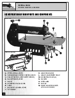
Page 8: ...B C ON OFF SWITCH WITH SAFETY DEVICE D BLADE TENSION LEVER F BLADE G WORKPIECE HOLD DOWN H TABLE I BLADE TILT LOCKING LEVER J TILT HANDLE K ANGLE INDICATOR L ANGLE ADJUSTMENT SCALE M MOUNTING HOLES 4 N BLOWER O UPPER ARM P MOTOR Q BLADE HOLDER SOCKETS EX 21CE EX 30CE ONLY OPPOSITE SIDE VIEW A B C D G H I K L P N O Q EX 21CE shown 8 F J M ...

Page 9: ...S IN THE OFF POSITION AND THAT THE POWER CORD IS UNPLUGGED DO NOT PLUG IN OR TURN ON THE SCROLL SAW UNTIL YOU HAVE COMPLETED THE ASSEM BLY AND INSTALLATION STEPS DESCRIBED IN THIS SECTION OF THE MANUAL NOTE Unscrew the 4 shipping bolts and remove the saw from the protective plywood shipping base LIST OF CONTENTS QTY A SCROLL SAW 1 B POWER CORD 1 C HEX NUT 8 D LEVELING FOOT 4 E 3 MM ALLEN KEY 1 F B...

Page 10: ...OFF IMMEDIATELY AND READJUST THE LEVELING FEET AS NEEDED TO STABILIZE THE SCROLL SAW ON THE BENCH OR WORK SURFACE MOUNTING TO A WORK SURFACE If a permanent shop placement is practical consider removing the leveling feet on the base and drilling matching through holes in the mounting surface of your workbench or stand to bolt the saw in place hardware not included on your workbench If a permanent i...

Page 11: ...k your local tool or scroll saw dealer for suggestions for unpinned 5 scroll saw blades based on what is available in your area BLADE SELECTION CHOOSING INSTALLING A SAW BLADE Some general guidelines to consider when choosing blades Wide thick blades with coarse teeth are suited to cutting straight lines and sweeping curves but will not turn tight corners They will cut aggressively and leave a fai...

Page 12: ...r pearl etc For tight radius work with thin materials 3 32 1 2 wood veneer wood bone fiber plastic etc For close radius work in materials 1 8 or thicker Good for sawing hard and soft woods bone horn plastic etc Popular sizes for cutting hard and soft woods 3 16 up to 2 Also cuts plastic paper felt bone etc SKIP TOOTH REVERSE TOOTH Same applica tions as Skip Tooth blades BLADE WIDTH THICKNESS TEETH...

Page 13: ...r saw and gives you up to 3 inch cutting capacity when needed Note Do not over tension the knob as this can cause premature wear and damage to the machine INSTALLING OR CHANGING BLADES ALWAYS TURN OFF AND UNPLUG THE MACHINE BEFORE REMOVING HANDLING OR CHANGING BLADES 1 Remove an installed worn or broken blade by flip ping the blade tension lever forward position 1 then loosening the thumbscrews A ...

Page 14: ...l knob B is located on the top of the machine To increase blade speed turn the control knob clockwise To decrease blade speed turn the control knob counterclockwise Blade speed selection is subjective and is dependant on a variety of factors type and thickness of material being cut type of blade being used feed rate required finish quality as well as experience personal preference and com fort lev...

Page 15: ...r feed rate as needed to allow the blade teeth time to make the cut Avoid coming to a complete stop whenever possible as this can leave burn marks on the workpiece and also makes it more difficult to get the piece re started and moving through the cut again Avoid forcing through a curve cut as this can cause the blade to twist and cut off track or may even cause the blade to break The EX 16CE has ...

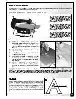
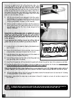
Page 16: ...kpiece to the scroll saw This will keep you from going back and forth from the saw to the drill press To prolong blade life by limiting unnecessary cutting drill your guide holes as close as possible to your reference lines D 3 Release tension on the blade by flipping the blade tension lever forward 4 Loosen the thumbscrew on the lower blade mount located under the table to release the blade from ...

Page 17: ...tures of the Scroll Saw is the ability to tilt the head of the saw in order to make angle or bevel cuts The table and the workpiece always stay horizontal parallel to the floor while the blade tilts keeping your hands in the same comfortable cutting position as they would normally be for regular right angle cuts Because you are not fighting gravity or working with your hands or wrists bent in awkw...

Page 18: ...all dab of grease after every 10 15 hours of use or as needed depending on the frequency of use of the saw UPPER ARM ADJUSTMENT FOR FRET WORK Over time and with normal wear the upper arm adjustment screw A may require slight adjustment in order to hold the arm in the raised position when the arm is lifted by the operator To reset the adjustment screw 1 Remove the blade and with the upper arm down ...

Page 19: ...oiled or greased F Underside View RECOMMENDED OPTIONAL ACCESSORIES We offer some optional accessories available from your local General International dealer for increased con venience productivity accuracy and safety when using your scroll saw For more information about our products please visit our website at www general ca Notes 19 BLADE GUARD EX 02 Optional upper and lower blade guard assembly ...

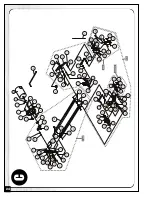
Page 20: ... 5 3 3 2 2 0 0 5 5 3 3 3 3 2 2 3 3 8 8 3 3 7 7 3 3 0 0 3 3 1 1 3 3 7 7 5 5 8 8 5 5 9 9 5 5 0 0 6 6 1 1 6 6 2 2 6 6 3 3 6 6 4 4 6 6 6 6 6 6 7 7 6 6 8 8 6 6 9 9 6 6 0 0 7 7 0 0 7 7 7 7 6 6 2 2 7 7 5 5 5 5 7 7 7 7 5 5 4 4 6 6 5 5 3 3 2 2 8 8 4 4 7 7 4 4 5 5 4 4 5 5 4 4 6 6 4 4 1 1 4 4 0 0 4 4 9 9 4 4 5 5 3 3 1 1 7 7 5 5 6 6 0 0 7 7 5 5 7 7 3 3 7 7 4 4 7 7 EX21A 31 32CE EX21 A58ASSY 20 A ...

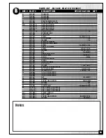
Page 21: ...OCKET 1 38 EX21 A38 FUSE 5 AMP 20 X 5 MM GLASS FUSE 1 40 EX21 A40 GEAR COVER 1 41 EX21 A41 NUT 3 8 X T5 5 1 45 EX21 A45 ALLEN SCREW 10 32 X 2 1 4 4 46 EX21 A46 SCREW 3 8 X 5 8 1 47 EX21 A47 WASHER 8 3 48 EX21 A48 SCREW 8 32 X 1 4 3 49 EX21 A49 MOTOR LABEL 1 50 EX21 A50 WARNING LABEL 1 51 EX11 A51 NYLON NUT 10 32 4 52 EX21 A52 NYLON NUT 1 4 20UNC 2 53 EX21 A53 LOCK WASHER 1 4 1 54 EX21 A54 FLAT WAS...

Page 22: ...2 6 6 3 3 7 7 1 1 8 8 1 1 4 4 1 1 1 1 2 2 0 0 2 2 3 3 1 1 6 6 2 2 7 7 2 2 8 8 2 2 7 7 3 3 2 2 2 2 3 3 2 2 4 4 2 2 5 5 2 2 8 8 3 3 9 9 3 3 0 0 4 4 2 2 2 2 2 2 1 1 5 5 1 1 5 5 1 1 4 4 4 4E E X X 1 1 6 6 4 4 3 3E E X X 1 1 6 6 4 4 4 4E E X X 1 1 6 6 2 2 1 1 4 4 3 3E E X X 1 1 6 6 2 2 1 1 4 4 3 3E E X X 1 1 6 6 2 2 1 1 4 4 3 3E E X X 1 1 6 6 4 4 4 4E E X X 1 1 6 6 5 5 1 1 4 4 4 4E E X X 1 1 6 6 5 5 1 ...

Page 23: ...X21 B19 NUT 1 4 20UNC 12 20 EX21 B20 ANGLE INDICATOR 1 21 EX21 B21 ALLEN SCREW 1 4 20 X 1 2 22 EX21 B22 E RING ETW 3 1 23 EX21 B23 TILT DETENT BARREL 1 24 EX21 B24 SPRING 1 25 EX21 B25 DETENT PLUNGER 1 26 EX21 B26 TILT HANDLE 1 27 EX21 B27 WASHER 1 4 X 16 X 3 1 28 EX21 B28 BLADE TILT LOCKING LEVER 1 29 EX21 B29 FLAT HEAD SCREW 1 4 20 X 3 4 4 35 EX21 B35 LEVELING FOOT 3 8 16 X 1 1 4 4 36 EX16 B45 T...

Page 24: ...N 5 4 N 5 4 4 4 33 C 17 64 41 C 36 C C C C C C C C C C C C C C C C C C C64A 46A 36ASSY 27C 24 C ...

Page 25: ... 36ASSY EX21C 36ASSY BLADE CHUCK BOTTOM ASSEMBLY 1 37 EX21 C37 SET SCREW M6X8 2 38 EX21 C38 BLADE CLAMP THUMB SCREW 2 39 EX21 C39 BLADE 1 40 EX21 C40 ALLEN KEY 3MM 1 41C EX21 C41C CLAMP BRACKET 1 42 EX21 C42 SET SCREW 1 4 20UNC 1 43 EX21 C43 SPRING 1 44 EX21 C44 TENSION LEVER FOR EX 16 EX 21 5MM 1 EX30 C44 TENSION LEVER FOR EX 30 7MM 1 45N EX21 C45 SCREW POST 5 X 18 1 46 EX21 C46 SLIDING BRACKET 1...

Page 26: ... 8360 Champ d Eau Montreal Quebec Canada H1P 1Y3 Tel 514 326 1161 Fax 514 326 5565 Parts Service Fax 514 326 5555 Order Desk orderdesk general ca www general ca MODELS EX 16CE EX 21CE EX 30CE MODEL EX 21CE SHOWN ...

Reviews: